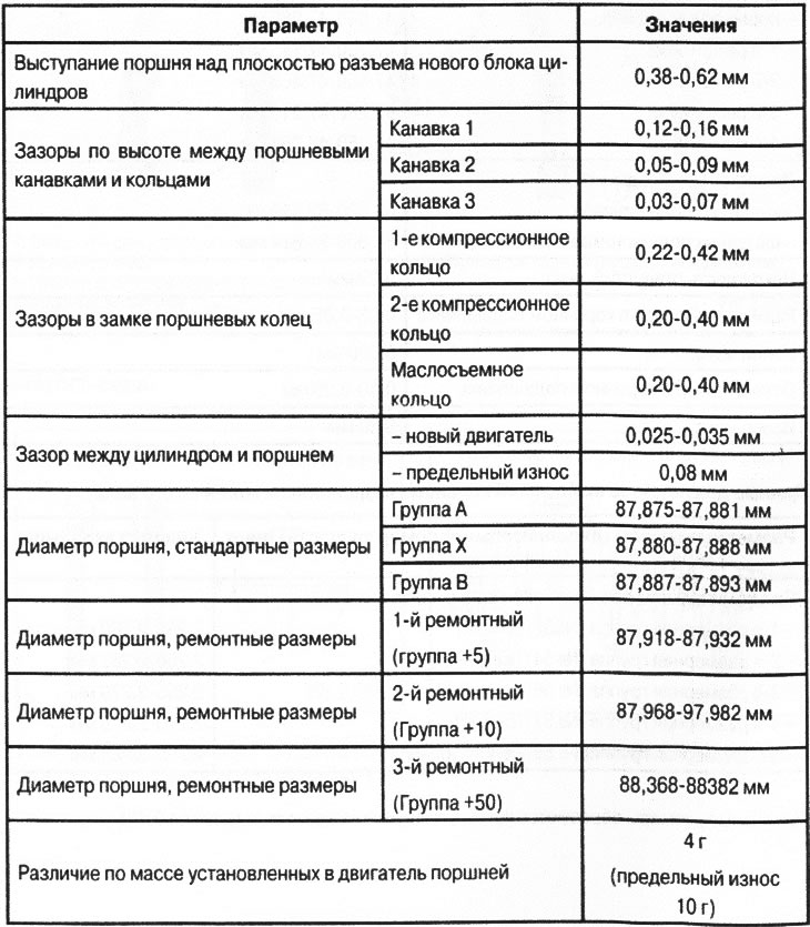
VN 2.069
1. Crank hall (A 646 031 07 01) replaced subsequently by (А646 031 04 01 +001 А108 991 00 67) As an option: (A 611 031 05 01 001 001 001)
1. Crankshaft (A 611 031 05 01) replaced subsequently by (А646 031 04 01 +001 А108 991 00 67) As an option: (A646 031 07 01)
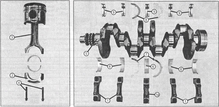
1. Crankshaft (A 646 031 04 01)
2. Flywheel pin
3. Segment key
4. Timing sprocket block
5. Crankshaft pulley with vibration damper
6. Screw securing the pulley to the crankshaft
7. Washer
8. Flywheel
9. G40 flywheel ring gear
10. Washer (MF4)
11. Screw for fastening the flywheel M10x1x28.5
12. Crankshaft main bearing shells, set, standard size 58.00 mm
13. Thrust bushings, set 2.15 mm
14. Balancing mechanism
15. Balancer drive gear
Note: the figure shows a crankshaft variant equipped with a balancer drive gear and a balancer mechanism, which are not installed on the OM646 engines used for the described vehicle. These nodes are shown for the information of auto mechanics.
We recommend paying attention to the number of crankshaft modifications, information about which is provided for a better understanding of the variety of designs of the OM 646 engine family.
Checking the condition of parts of ShPG and KShM consists in carrying out the following work.
- Checking the condition of the cylinder block.
- Check the condition of the crankshaft.
- Checking the condition of the connecting rods.
Repair of ShPG and KShM consists in carrying out the following works.
- Repair of the cylinder block, including boring of cylinder liners to the repair size or replacement of liners, machining of the upper plane, replacement (if necessary) cooling jacket plugs, replacement of oil channel plugs (after cleaning the oil channels).
- Repair of the crankshaft, which consists in grinding the necks of the plain bearings to repair dimensions, cleaning the oil channels and dirt traps.
- Selection of pistons based on the results of the repair of the cylinder block.
- Selection of liners for main and connecting rod bearings based on the results of checking and processing the crankshaft.
- Replacement of the upper bushings of the connecting rods according to the results of checking the connecting rods.
Checking the condition of the cylinder block
Check of a condition of a mirror of cylinders
Checking the condition of the cylinder block consists in carrying out the following work.
- Visual check of a condition of a mirror of cylinders.
- Measurements of the diameter of the cylinders.
- Visual inspection of the condition of the upper plane of the connector (with MCC).
- Measurement of deviations from the parting planes with the cylinder head, with the oil sump and with manifolds.
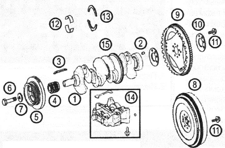
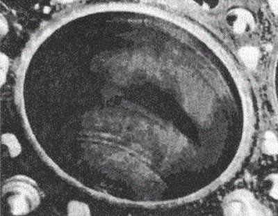
Visual check of a condition of a mirror of cylinders
Glossy areas, abrasions, individual shiny areas, for example, in the middle of the cylinder or in the area of \u200b\u200bthe cylinder head screws. The cylinder block is ready for further use.
VN 2.070
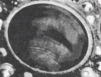
Visible marks, friction marks starting at the top dead center area of the upper piston ring and descending downwards.
Intangible traces of dry friction resulting from the washing away of the oil film by the fuel, for example, during frequent starts of a cold engine in short-distance vehicle operation.
Such «smoothed»» traces of friction that occur on the mirror of the cylinder, mainly in the area of \u200b\u200bthe screws for fastening the cylinder head and in the area of \u200b\u200blateral pressure of the piston skirt, are within the normal range.
Piston rings are not damaged.
The cylinder block is ready for further use.
VN 2.071
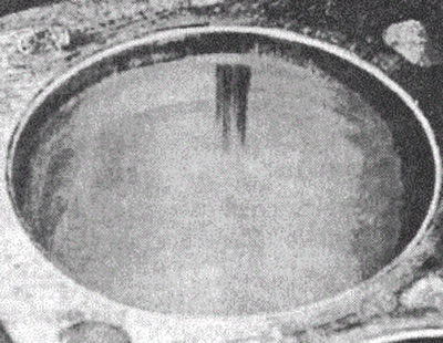
Ring-shaped visible impressions on the cylinder mirror in the area of the upper and lower dead spots of the piston rings are not a sign of a malfunction.
The cylinder block is ready for further use.
VN 2.072
Cylinder diameter measurement
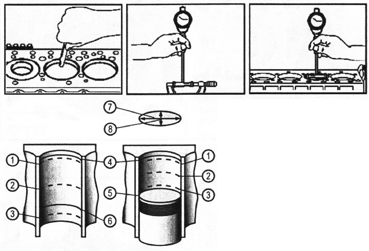
VN 2.073
1. Cylinder diameter measuring point
2. Cylinder diameter measuring point
3. Cylinder diameter measuring point
4. Top dead center of the top compression ring
5. Bottom dead center of the top edge of the piston
6. Bottom dead center of the low-removable ring
7 and 8. Mutually perpendicular measurement directions (along and across the axis of the engine)
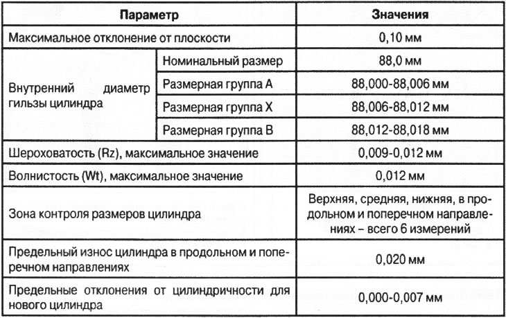
Control parameters of cylinders
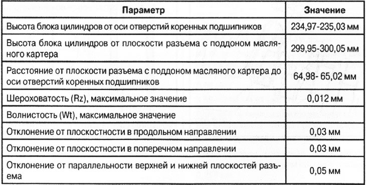
Control parameters of planar elements of the cylinder block
Checking and processing the upper plane of the cylinder block
VN 2.074
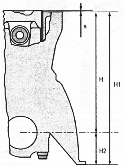
A. Piston protrusion
H. The height of the cylinder block from the axis of the holes of the main bearings
H1. The height of the cylinder block from the parting plane with the oil pan
H2. Distance from the plane of the connector with the oil pan to the axis of the holes of the main bearings
Selection of standard size pistons
When replacing liners, the cylinders are machined to a standard size. The diameter of the cylinders machined at the factory corresponds to three accuracy classes: A, B and X,
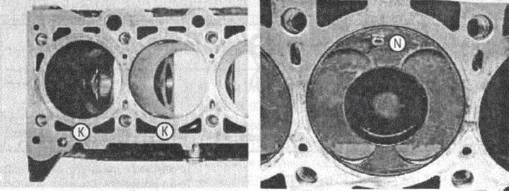
A label indicating the accuracy class of this cylinder is placed in the place indicated in the figure by the letter (TO).
Similar to engine cylinders, standard size pistons are also divided into three size groups: A, B and X. The piston size group is marked on the piston head at the point (N) (see fig. VN 2.075). When installing new parts of a standard size, the markings on the piston must match the markings on the cylinder block for each cylinder individually. The values of the control parameters of the pistons are presented in the table.
The selection of piston repair dimensions should be made based on the dimensions purchased for piston repair.
Further, the specialist who bores the cylinders should be guided by the normalized clearances in the cylinder-piston pair.
VN 2.075
Checking the condition of the crankshaft
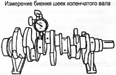
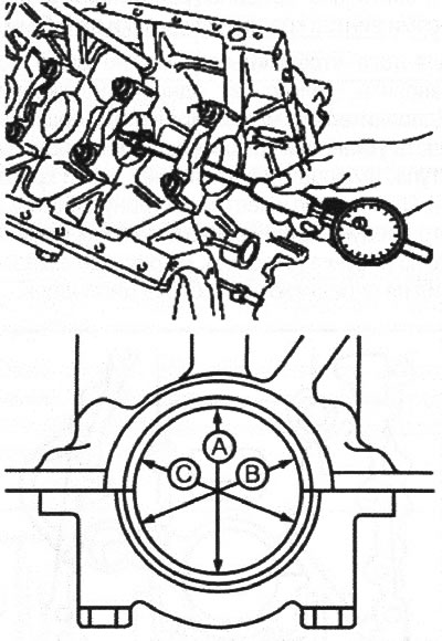
Checking the condition of the crankshaft consists in visually inspecting the shaft for damage and visible signs of wear, measuring the diameter of each journal with a micrometer, measuring the radial runout of the crankshaft journals using a dial indicator when installing the extreme main journals of the shaft on the measuring prisms.
VN 2.076
1. Main bearing caps
1a. No. 3 main bearing cap
2. Connecting rod bearing caps
3. Connecting rod
4. Connecting rod bearing cap screws
5. Crankshaft
6 Lower main bearing shells
7. Thrust bushings
8. Thrust bushings
9. Upper main bearing shells
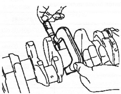
Measurement of crankshaft bearing journals
VN 2.077
VN 2.078
VN 2.079
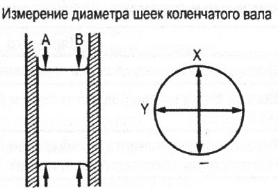
The measurement is made in points (A) And (IN) as shown in fig. VN 2.072, in two mutually perpendicular directions X and Y.
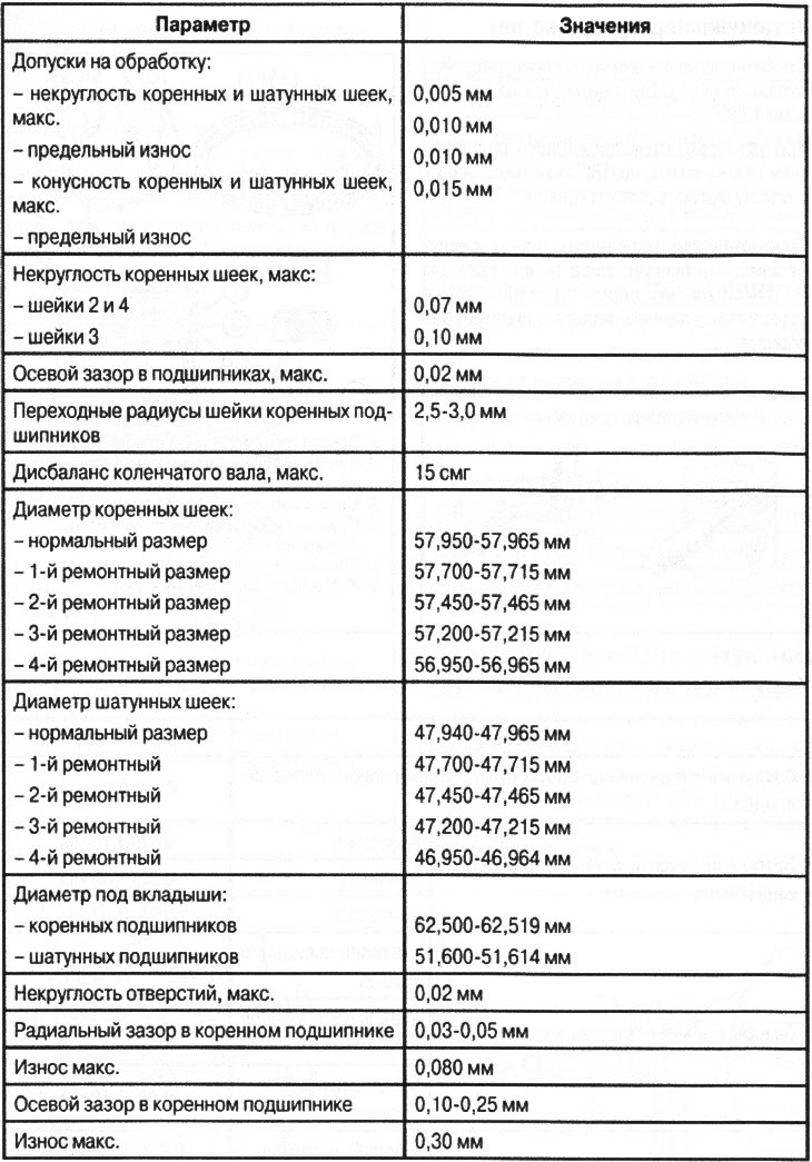
Control parameters of the crankshaft
Selection data for crankshaft main bearing shells
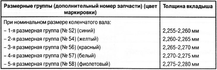
Repair dimensions are formed by thickening each insert by 0.125 mm.
Selection of liners of main bearings
The selection of liners is based on the results of an accurate measurement of the diameters of the crankshaft journals using the data table for the selection of liners.
In addition, you can use the method of determining the calculated clearance in the crankshaft bearings based on the measurement of the crankshaft and the holes of the main bearings with the liners installed.
To do this, measure the diameter of the holes in the seats for the liners in the direction (A) (e.g. 62.51 mm).
VN 2.080
Then measure the diameter of the crankshaft main journals (e.g. 57.95 mm).
Based on the measurements, the thickness of the liners can be determined.
For example:
62.51 mm (main bearing bore diameter) - 57.95 mm (main bearing journal diameter) - 4.55 mm.
From the result obtained, we subtract the average standard value of the clearance in the main bearing (0.03mm + 0.05mm): 2 = 0.04 mm):
4.55-0.04 = 4.51 mm.
The resulting number is twice the thickness of the liner, it should be divided by 2: 4.51: 2 = 2.255 mm.
Thus, the calculated required thickness of the liner in this example would be 2.255 mm.
After that, using the table, you should select the insert.
For example, with a thickness of 2.255 mm, you should choose the top and bottom liners with a blue mark, which corresponds to the 1st size group.
Note: This bearing selection method is suitable for standard crankshaft size.
If necessary, repair the worn crankshaft. You should choose a repair size and purchase the appropriate liners. Then - based on measurements of the actual hole diameter with liners installed (from tightened main bearing caps) to machine the crankshaft so that the value of the actual clearance in each bearing is within the standard limits (0.03-0.05mm).
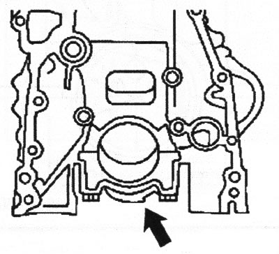
Installing main bearing caps
The axis of the mounting hole for the bushing in the main bearing cap is offset from the middle of the distance between the axes of the cap fastening screws by 0.5 mm, so that the cap can be installed in only one position. Additionally, you can check the correct installation of the cover by the orientation of the protrusion on the bottom of the cover. This protrusion has a characteristic shape and should be oriented as shown in the figure (arrow). The figure shows a view of the front of the cylinder block.
VN 2.081
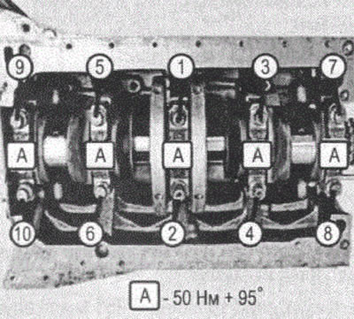
Tightening of screws of fastening of covers of main bearings of a cranked shaft
Scheme of applying the tightening forces of the screws for fastening the caps of the main bearings: 50 Nm + 95°.
The tightening sequence is shown in fig. VN 2.082,
VN 2.082
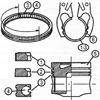
Pistons installation
Installation of piston rings
The joints of the piston rings must be located around the circumference of the cylinder at a distance of 120°.
When installing, position the joint of the spring expander at 180°with respect to the oil scraper ring connector.
When installing piston rings, measure the axial clearance between the ring and the wall of the piston groove and the clearance in the ring lock when the ring is installed in a cylinder without a piston.
VN 2.084
1 First compression ring (flat)
2. Second compression ring (with a conical surface)
3. Oil scraper ring (unitary)
4. Spring radial expander spiral
5. Piston
6. Tool for spreading rings
VN 2.085
Control parameters for pistons and piston rings