
Belt
Petrol models (M112/113)
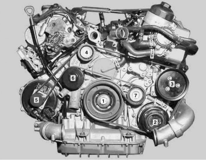
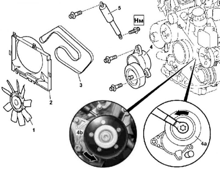
Details of installation of a belt of a drive of auxiliary units on petrol models (M112/113)
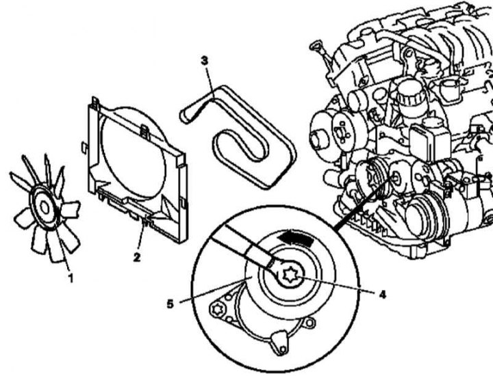
1. Remove the fan assembly (1 and 2) (see chapter Refrigeration, heating, ventilation and air conditioning systems).
2. Expanding the hairpin (4) tension roller (5) counterclockwise, loosen the belt (3) and block the roller with a 5 mm rod.
3. Remove the belt and carefully examine its condition (see chapter Ongoing care and maintenance). Replace if necessary.
4. Installation is carried out in the reverse order - start seating the belt from the tension roller and proceed in the order indicated in the illustration of the numbering. Don't forget to adjust the belt tension (see chapter Ongoing care and maintenance).
Laying scheme and order of landing on pulleys of a 6-rib belt for driving auxiliary units of M112 / 113 engines
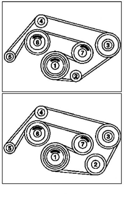
Above - Models without A/C; Below - Models with A/C; 1 - Crankshaft pulley; 2 - Guide pulley 2 / A/C compressor pulley; 3 - Steering pump pulley; 4 - Guide pulley; 5 - Generator pulley; 6 - Pulley for water pump and cooling fan; 7 - Tension roller
Diesel models
M612
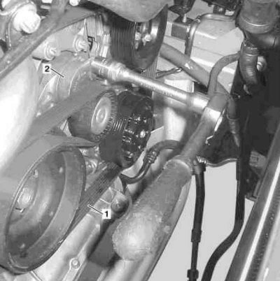
Installation details of the accessory drive belt on diesel models equipped with the M612 engine
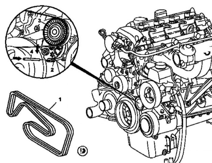
3 - Tension roller
1. Remove the viscous coupling of the cooling fan drive (see chapter Refrigeration, heating, ventilation and air conditioning systems).
2. Deploying the tensioner (2) and lock it with a pin (4), loosen, then remove the drive belt (1).
3. Examine the condition of the belt (see chapter Ongoing care and maintenance), replace if necessary.
4. Installation is carried out in the reverse order - start fitting the belt from the tension roller (see illustration below). Don't forget to adjust the belt tension (see chapter Ongoing care and maintenance).
Scheme of laying the drive belt of auxiliary units of the M612 engine
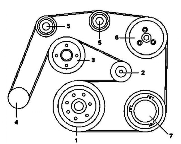
1 - Crankshaft pulley; 2 - Tension roller; 3 - Pulley for water pump and cooling fan; 4 - Generator pulley; 5 - Guide pulleys; 6 - Steering pump pulley; 7 - A/C compressor pulley
M628
Installation details of the accessory drive belt on diesel models equipped with the M628 engine
1. Remove the cooling fan shroud (see chapter Refrigeration, heating, ventilation and air conditioning systems).
2. Install the air conditioning radiator/condenser shield (metal or plastic sheet with dimensions of about 400x680x1 mm).
3. Remove the turbo intercooler (Intercooler) (see chapter Power supply and exhaust systems).
4. Expanding the tensioner (2) clockwise, loosen the belt (1) and remove it from the engine.
5. Examine the condition of the belt (see chapter Ongoing care and maintenance), replace if necessary.
6. Installation is carried out in the reverse order - start fitting the belt from the tension roller (see illustration below). Don't forget to adjust the belt tension (see chapter Ongoing care and maintenance).
Scheme of laying the drive belt of auxiliary units of the M612 engine
1 - Crankshaft pulley; 2 - K/V compressor pulley; 3 - Steering pump pulley; 4 - Guide pulley; 5 - Generator pulley; 6 - Water pump pulley; 7 - Intermediate roller
Tensioner
Petrol models (M112/113)
Installation details of the automatic accessory drive belt tensioner on gasoline models (M112/113)
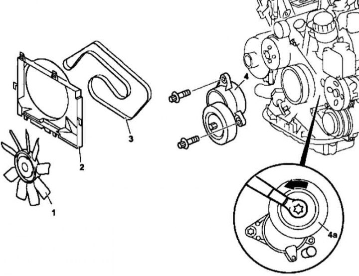
1. Remove the drive belt (3) (see above).
2. Deploy the idler (4a) counterclockwise and fix it with a 5 mm rod.
3. After unscrewing the self-tapping fixing screws, remove the tensioner (4) from the timing cover.
4. Installation is carried out in the reverse order.
Diesel models
M612
Installation details of the automatic belt tensioner for the drive of auxiliary units of the M612 engine
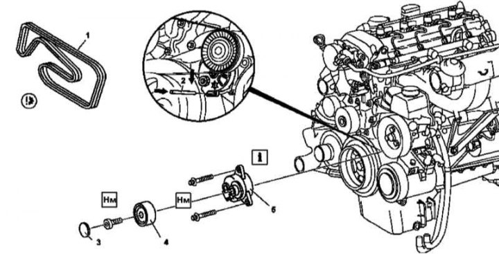
1. Remove the drive belt (see above).
2. Having unscrewed the fixing bolt, remove from the tensioner assembly (5) tension roller (4).
3. Remove pin (2), fixing tensioner (5) and, having unscrewed the fixing bolts, remove the latter from the timing cover.
4. Installation is carried out in the reverse order.
M628
Installation details of the automatic belt tensioner for the drive of auxiliary units of the M628 engine
1. Remove the turbo intercooler (Intercooler) (1) (see chapter Power supply and exhaust systems).
2. Remove the drive belt (2) (see above).
3. Remove the fixing screws (4), - access to the screw will open through a selection in the pulley (5) when turning the engine in the normal direction, - and remove the tensioner (3).
4. Installation is carried out in the reverse order.