
M112
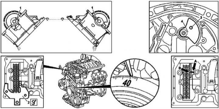
Checking the basic position of the balancing shaft of the M112 engine
1 - Grooves in camshafts; 2 - Blocking plate of the right camshaft; 3 - Hole in the rear counterweight; 4 - Rear counterweight; A - Pin in the crankcase; B - Risk on the front counterweight
1. Remove the transmission assembly (see chapter automatic transmission).
2. Remove the drive disk.
3. Check the basic position of the camshafts (see Section Checking and adjusting the basic position of the camshafts).
Note. On models equipped with an air pump, the right combination valve must also be dismantled, the gasket of which must be replaced without fail.
4. Install locking plates (2) on the right and left cylinder heads, filling them into the grooves (1) camshafts.
5. When the balance shaft is properly installed, the hole (3) in the rear counterweight (4) must be aligned with the socket in the engine crankcase, - insert a pin with a diameter of 8.40 ÷ 8.55 mm into the holes. Make sure also to balance the risks (IN) on front counterweight with pin (A) in the crankcase, - the risk and pin are located approximately 22 cm below the mating surface of the head and are viewed through a window in the left timing cover.
6. If the basic setting is violated, the balancing shaft must be replaced.
7. Reinstall all removed components in reverse order of removal.
M628
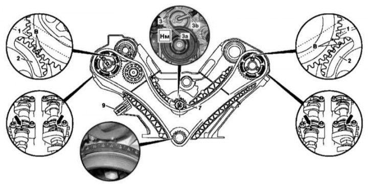
Checking the basic position of the balancing shaft of the M628 engine (1 of 2)
1 - Intake camshaft gear; 2 - Gear wheel of a final camshaft; 3 - Cover; 3a - Lower bolt; 3b - Top bolt; 5 - Spring; 7 - Asterisk of a balancing shaft; 9 - Setting marks
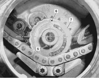
Checking the basic position of the balancing shaft of the M628 engine (2 of 2)
5 - Spring
6 - Marking
7 — an asterisk of a balancing shaft
1. Remove cylinder head covers (see illustrations Installation details of the cylinder head covers of the M682 engine (1 of 2) and Installation details of the cylinder head covers of the M682 engine (2 of 2)).
2. Remove the intercooler (Intercooler) turbocharging systems (see chapter Power supply and exhaust systems).
3. Remove the bottom bolt (3a) lids (3), - Turn the crankshaft in the normal direction to gain access to the bolt.
4. Bring the piston of the first cylinder to the TDC position.
5. Turn out the top bolt (3b) and remove the cover (3).
6. Remove the centrifuge.
7. Make sure the tensioner (9) provides the required tension force of the gas distribution chain.
8. Install the cover on the crankcase (3) and secure it with the top bolt (3b).
9. Rotate the crankshaft two full turns in the normal direction, again bringing the piston of the first cylinder to the TDC position.
10. Remove the cover again (3).
11. Make sure the basic setting of the camshafts is correct (see Section Checking and adjusting the basic position of the camshafts).
12. Check the correctness of the basic setting of the balancing shaft, the spring (5) which should occupy the position shown in the picture, and the marking (6) on an asterisk (7) be slightly out of position «at 12 o'clock».
13. Acting in the reverse order of dismantling, install the removed components in their places.
14. Finally, read the DTCs and clear the OBD memory using the STAR DIAGNOSIS scanner (6511 1801 00) (see chapter Engine Electrical Systems).