
Compression pressure test
Note. An assistant will be required to perform the compression test procedure.
Compression pressure measurement provides an overview of the current condition of internal engine components such as cylinder head gaskets, valve train components, pistons and piston rings. Analysis of the test results allows you to determine whether the engine needs a major rebuild, or simply replacing the head gasket is sufficient. The measurement is made using a compression gauge.
Note. For diesel engines, a compression gauge with a measurement limit of up to about 40 atm is required.
Warm up the engine to normal operating temperature (about 80°С), make sure the battery is fully charged.
Petrol models
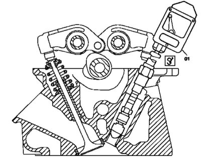
To measure the compression pressure, use a meter equipped with a remote starter switch (shown on model 202).
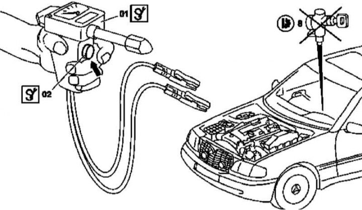
01 - Compressometer
02 - Remote starter switch
8 - Ignition switch
1. Stop the engine and, in accordance with the package, remove the air cleaner assembly (see chapter Power supply and exhaust systems).
2. Remove the spark plugs one by one (see chapter Engine Electrical Systems).
3. Remove the key from the electronic ignition switch (EIS).
4. Prepare a compression tester equipped with a remote starter switch
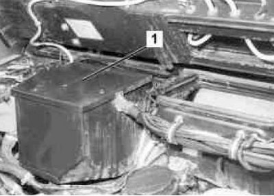
5. Remove the cover (1) control module mounting block
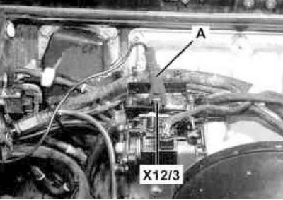
6. Connect clamp (A) meter to terminal X12/3.
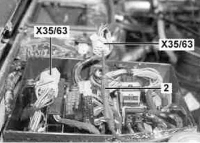
7. Disconnect connector X35/63 and connect the adapter cable equipped with a 6-pin plug to it (2), - connect the other end of the wire to the compression gauge wire
Attention! When measuring compression, do not crank the starter with the ignition switch!
8. Firmly press the measuring tip against the bottom of the spark plug niche of the first cylinder.
9. Fully open the throttle and, cranking the engine with a starter activated from the button of the remote switch of the compression gauge, read the readings of the latter. Record the measurement result.
Note. To remove carbon deposits from the cylinder walls, the engine should be rotated for about 5 seconds.
10. Proceeding in a similar manner, alternately measure the compression pressure in the remaining engine cylinders.
11. Stop the engine, disconnect the compression tester, screw in the spark plugs and reinstall the air cleaner.
Diesel models
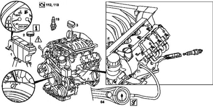
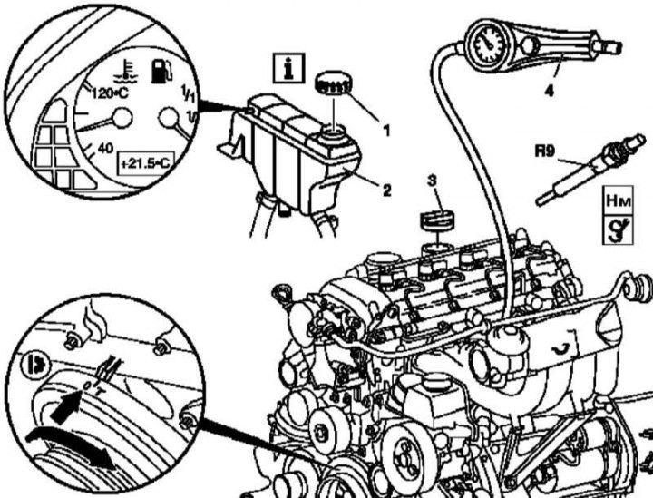
Checking Compression Pressure on Diesel Models Equipped with 612 Series Engine
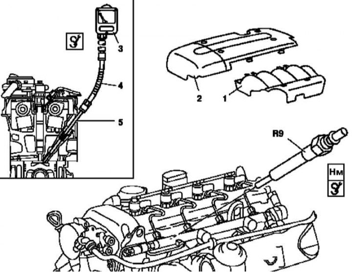
1 - Air distributor cover
2 — Overlay of a cover of a head of cylinders
3 - Compressometer
4 - Connecting hose
5 - Threaded nozzle
R9 - Glow Plug
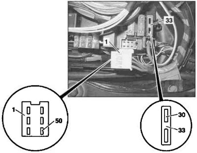
Checking Compression Pressure on Diesel Models Equipped with 628 Series Engine
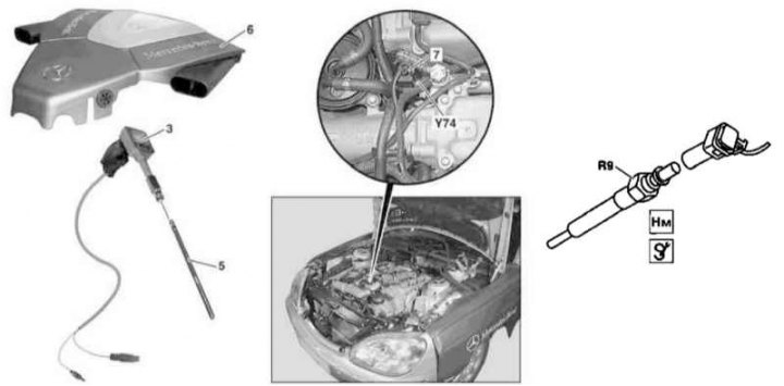
3 - Compressometer
5 - Threaded nozzle
6 - Assembly of the air cleaner
7 - Pin connector
R9 - Glow Plug
Y74 - Pressure control valve
1. Stop the engine and remove the air distributor cover of the duct sleeve and the cylinder head cover trim / air cleaner assembly (see chapter Power supply and exhaust systems). turn the key «ignition» into position 0.
M612
To measure the compression pressure, use a meter equipped with a remote starter switch (shown on model 202)

01 - Compressometer
02 - Remote starter switch
8 - Switch «ignition»
Y74 - Pressure control valve
1. Remove glow plugs (see chapter Engine Electrical Systems).
2. Prepare a compression tester equipped with a remote starter switch.
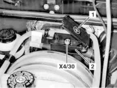
3. Remove the cover (1) outdoor start pads (2) and connect the meter clamp to terminal X4/30
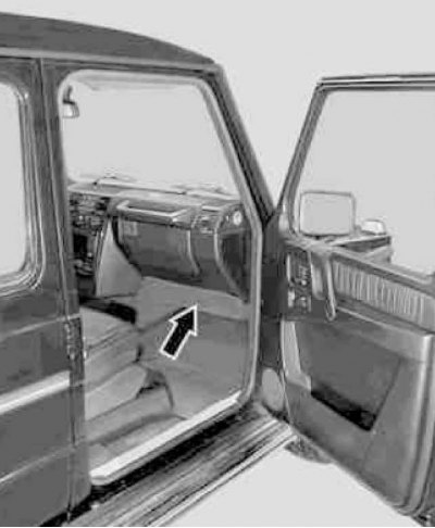
4. Remove the cover (arrow) right under the dashboard
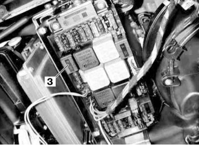
5. Remove the relay from the mounting block (3) starter, the installation point of which is marked with the letter S.
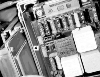
6. To the block (4) relay (letter S on the board of the mounting block) connect the adapter cable of the compression tester
Attention! When measuring compression, do not turn the starter from the switch «ignition»!
7. Using a threaded nozzle with a flexible connecting hose, connect the compression tester to the spark plug hole of the first cylinder (see illustration Checking Compression Pressure on Diesel Models Equipped with 612 Series Engine).
8. Proceed further in accordance with the instructions given for gasoline engines - there is no need to depress the gas pedal / open the throttle.
Note. The engine must be rotated at least eight times for the measurement to be taken.
M628
1. Disconnect the pressure control valve connector (see illustration Checking Compression Pressure on Diesel Models Equipped with 628 Series Engine) and remove glow plugs (see chapter Engine Electrical Systems).
2. Prepare a compression tester equipped with a remote starter switch (see illustration Checking Compression Pressure on Diesel Models Equipped with 628 Series Engine) and, proceeding further in accordance with the instructions (on the example of models 220.028/128 equipped with engines 629.960), connect it to the corresponding fuse terminals in the right front mounting block.
3. Remove the cover of the right front fuse and relay mounting block (K40/7) and remove the maxi fuse from its socket (60A) fan of the engine cooling system, then disconnect the white connector (1)
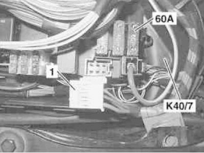
4. Connect the adapter wires of the compression tester to the base terminal (30) fuse holder (33) and terminal (50) white connector (1)
Attention! When measuring compression, do not turn the starter from the switch «ignition»!
5. Using a threaded nozzle with a flexible connecting hose, connect the compression tester to the spark plug hole of the first cylinder (see illustration Checking Compression Pressure on Diesel Models Equipped with 628 Series Engine).
6. Proceed further in accordance with the instructions given for gasoline engines - there is no need to depress the gas pedal / open the throttle.
Note. The engine must be rotated at least eight times for the measurement to be taken.
7. Alternatively, the compression pressure can be measured using the STAR DIAGNOSIS diagnostic reader - follow the instructions supplied with the device.
All models
1. Compare measurement results with requirements Specifications.
2. The maximum allowable pressure difference in individual cylinders can be 1.5 atm (for petrol engines) and 3.0 atm (for diesel engines).
3. Compression in a serviceable engine grows very quickly. A low reading after the first cycle, increasing with successive cycles, indicates worn piston rings. A low value after the first cycle, not increasing after the next, signals that either the valves are leaking or the head gasket is blown (Could also be a cracked head). The presence of soot on the valve plates can lead to a decrease in compression.
4. Please note that due to different starter rotation speeds on different models, the results obtained as a result of measurements may vary. The results obtained when measuring compression should be approximately the same for all cylinders.
5. If the pressure in any cylinder is at or below the minimum allowable pressure, follow these steps to determine the cause. Pour a teaspoon of engine oil into the cylinder through the spark plug hole and repeat the compression measurement.
6. If the addition of oil temporarily improves compression, the reason for the decrease is most likely piston, ring or cylinder wear. If there is no increase in compression, then it can be assumed that the cause is valve leaks or a broken head gasket.
7. Low compression in two adjacent cylinders is almost certainly the result of a blown head gasket. The presence of coolant in the combustion chambers or in the crankcase will confirm this assumption.
8. If the compression in one of the cylinders is about 20% lower than in the others, besides, the idle speed is unstable, then the cause may be excessive wear of the camshaft cam.
9. After completing the check, reinstall the spark plugs, connect the wiring to them, on gasoline engines, restore the original coil connection (ek) ignition. Reinstall the plastic engine cover and fuel pump fuse.
Checking cylinders for leaks
During this test, the rate of exit from the cylinders of the compressed air pumped into them and the leaks directly are determined. This test is an alternative to the compression test. Moreover, from many points of view, it is much more effective, since visually identifying the source of a leak is easier than comprehending the results of a compression measurement.
All models
1. Warm up the engine to normal operating temperature (80°C), then mute it.
Petrol models
Checking the cylinders of gasoline engines for leaks
1. Gently rotate the cover equipped with a built-in latch (2) expansion tank (1) cooling system to the first stop, wait for the pressure to be released, then unscrew the cap completely.
2. Remove the spark plugs (19).
3. Turning the engine by the central bolt of the crankshaft in the normal direction, bring the piston of the cylinder to be checked to the TDC position of the end of the compression stroke, then connect a special tester to the corresponding candle hole (04), having previously calibrated it, - act in strict accordance with the instructions attached to the device.
4. Remove the engine oil filler cap (3).
5. Supply compressed air to the cylinder and, according to the readings of the meter, evaluate the rate of pressure relief. Record the result.
Note. If during the check the crankshaft begins to rotate, block it with a special tool (see Sections Checking and adjusting the basic position of the camshafts and Checking the basic position of the balancing shaft (only M112 and 628 engines)).
6. Repeat the test for the remaining cylinders - proceed in the order of ignition (see chapter Engine Electrical Systems).
7. Disconnect the meter and replace the spark plugs.
Diesel models
Checking diesel engine cylinders for leaks
1. Turn the lid (1) expansion tank (2) coolant system half a turn counterclockwise, wait for pressure to be released, then remove the cap completely.
2. Remove engine trim panels (M612) / air cleaner assembly (M628).
3. Remove glow plugs (R9).
4. On models equipped with a 628 series engine, remove the charge air cooler (see chapter Power supply and exhaust systems).
5. On models equipped with a 612 series engine, remove the cooling fan viscous coupling (see chapter Refrigeration, heating, ventilation and air conditioning systems).
6. Turning the engine by the central bolt of the crankshaft in the normal direction, bring the piston of the cylinder to be checked to the TDC position of the end of the compression stroke, then connect a special tester to the corresponding candle hole (04), having previously calibrated it, - act in strict accordance with the instructions attached to the device.
7. Proceed in the same manner as described above for gasoline engines (see paragraphs 4 to 7 Check cylinders for leaks - petrol models).
All models
1. Compare test results with requirements Specifications. Carry out necessary repairs if necessary.
Checking cylinders with a probe lamp
Petrol models
Checking the cylinders of gasoline engines with a probe lamp
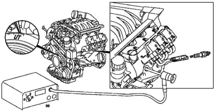
1. Turn out spark plugs.
2. Turning the engine in the normal direction by the central bolt of the crankshaft, bring the piston of the cylinder to be checked to the BDC position.
3. Acting strictly in accordance with the manufacturer's instructions, connect the special test lamp (05), put its flexible light guide into the appropriate spark plug hole and visually assess the condition of the cylinder walls, which should have a matte finish without traces of honing notches.
4. In a similar manner, inspect the walls of the remaining cylinders (in ignition order).
5. If necessary, remove the engine, cylinder heads and make a more detailed direct inspection of the cylinder mirrors and the necessary reconditioning.
Diesel models
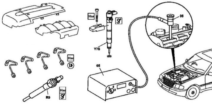
1. Remove the key from the lock «ignition».
2. Remove cylinder head trim panels (M612) / air cleaner assembly (M628).
3. Remove glow plugs (R9).
4. Remove nozzles (Y76) (see chapter Power supply and exhaust systems).
5. On models equipped with a 628 series engine, remove the charge air cooler (see chapter Power supply and exhaust systems).
6. On models equipped with a 612 series engine, remove the cooling fan viscous coupling (see chapter Refrigeration, heating, ventilation and air conditioning systems).
7. Turning the engine at the crankshaft center bolt in the normal direction, bring the piston of the cylinder to be checked to the BDC position.
8. Proceed in the same manner as described above for gasoline engines (see paragraphs 3 to 5).