
Note. The engine is removed complete with transmission.
Disconnecting the electrical wiring
Petrol models
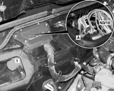
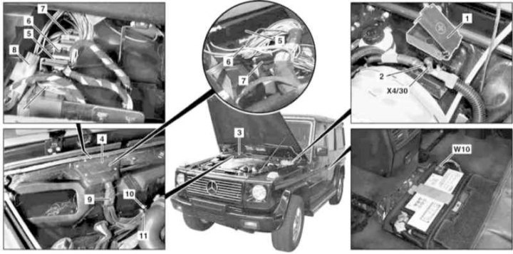
The layout of the main components of the engine wiring (1 of 8)
1 — Panel cover of an electrical wiring of the engine (in the cabin)
A - Contact connector
N3/10 - ME-SFI control module
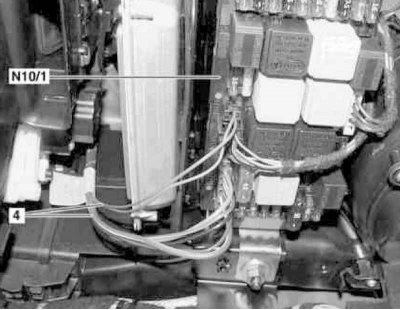
The layout of the main components of the engine wiring (2 of 8)
4 - Wiring braid
N10/1 - Front SAM
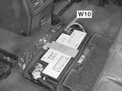
The layout of the main components of the engine wiring (3 of 8)
W10 - Battery Ground
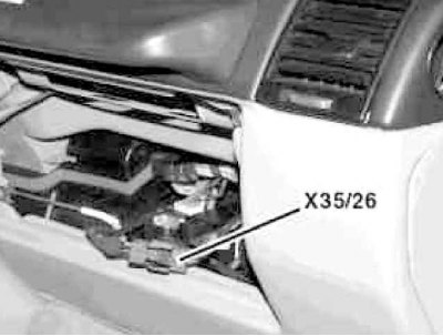
The layout of the main components of the engine wiring (4 out of 8)
X35 / 26 - Separation unit of the modular block / engine
The layout of the main components of the engine wiring (5 out of 8)
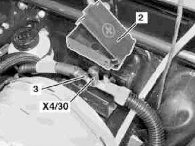
2 - Cover of the connection unit of the auxiliary power source for emergency start
3 - Terminal 30 wire
Х4/30 - Terminal block (engine circuit 30)
The layout of the main components of the engine wiring (6 out of 8)
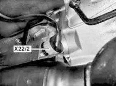
X22 / 2 - Automatic transmission connector
The layout of the main components of the engine wiring (7 out of 8)
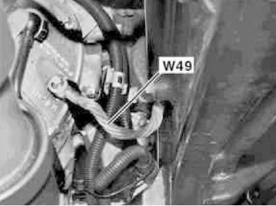
W49 - Transmission ground bus
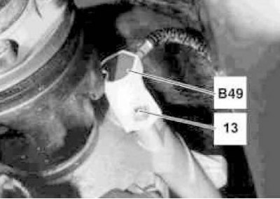
Disconnecting the main engine wiring harnesses (8 out of 8)
13 - Bolt
B49 - Speed sensor at the output of the transmission
1. On models of the corresponding configuration (code ET2) activate the service mode of the TELE AID emergency call system (see Section Activation / deactivation of the service mode of the TELE AID emergency call system).
2. Turn on the auxiliary battery and connect it to the standard battery, then disconnect the negative wire from the latter, insulate the pole terminal. If the battery is removed from the vehicle, disconnect the positive cable from the battery as well.
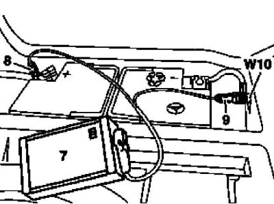
7 - Auxiliary battery
8 - Module positive wire terminal
9 - Terminal of the negative wire of the module
W10 - Battery Ground
3. Remove the air path resonator chamber with water collector (see chapter Power supply and exhaust systems).
4. Remove the panel cover located in the passenger compartment (1) engine wiring.
5. Disconnect the wiring connectors (A) on the ME-SFI control module (N3/10), - push down the latch and turn the locking lever.
6. Remove the glove box (see chapter Body).
7. Disconnect the connector on the module/engine separation assembly (Х35/26).
8. Disconnect the wiring (4) front module of perception and signal activation (SAM) (N10/1).
9. Pull the cabin wiring harness of the engine through the through hole in the body panel - try not to damage the insulation.
10. Disconnect the lambda probe electrical wiring connectors (G3/3), G3/4, G3/5 and G3/6) (see illustration Powertrain Installation Details on Gasoline Models).
11. Remove the left ignition coil (see chapter Engine Electrical Systems).
12. Open the lid (2) connection point for auxiliary power supply for emergency start.
13. Loosen the wire (3) from terminal 30 of the terminal block (Х4/30) circuit 30 of the engine.
14. Disconnect the ground bus W11/5 from the starter.
15. Disconnect the wiring connector (Х22/2) on the transmission.
16. Unscrew the ground bus from the frame (W49) transmission.
17. Remove the bolt (13) and remove the speed sensor at the output of the transmission (B49) (speed sensor), - prepare a replacement sealing ring.
18. Installation is carried out in the reverse order, - with the appropriate configuration (code ET2) deactivate the service mode of the TELE AID system (see Section Activation / deactivation of the service mode of the TELE AID emergency call system).
19. Finally, read the DTCs and clear the OBD memory using the STAR DIAGNOSIS scanner (6511 1801 00) (see chapter Engine Electrical Systems).
Diesel models
M612
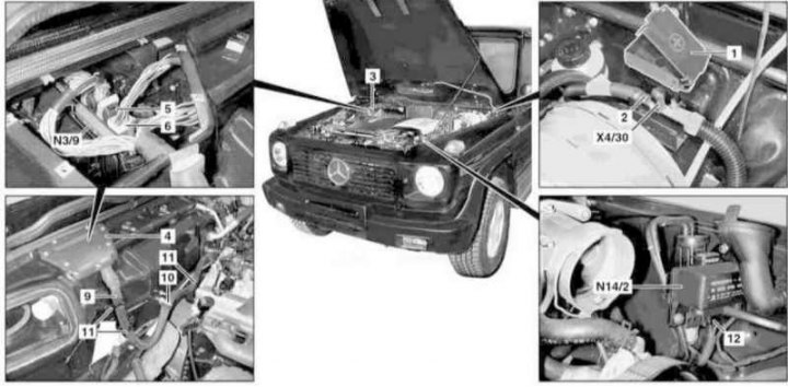
Layout of the main components of the electrical wiring of the M612 engine (1 of 3)
1 - Cover; 2 - Terminal 30 wire; 3 - Resonator chamber of the air path with a water collector; 4 - Cover; 5, 6, 12 - Pin connectors; 9 Braid of electrical wiring of the engine; 10 - Retainer; 11 - Bandage; N3/9 - CDI control module; N14 / 2 - Output of the preheat system; X4/30 - Terminal block for connection of auxiliary power supply for emergency start
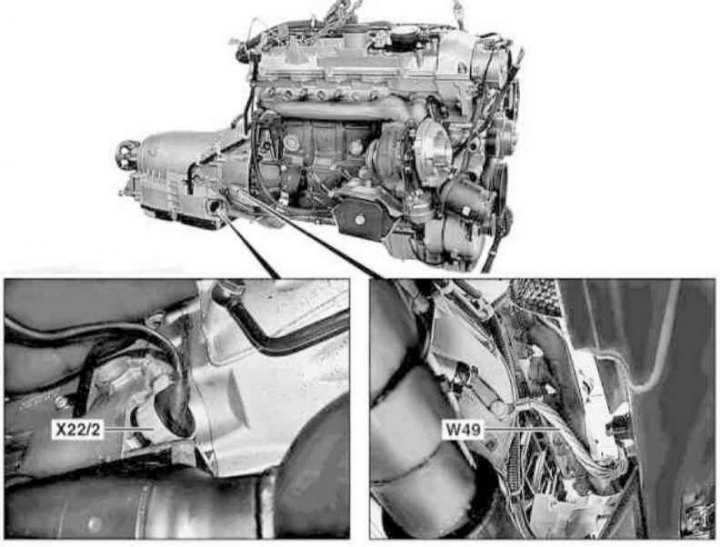
Layout of the main components of the electrical wiring of the M612 engine (2 of 3)
W49 - Transmission ground bus
X22 / 2 - Central automatic transmission connector
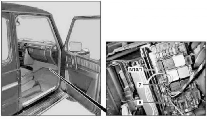
Layout of the main components of the electrical wiring of the M612 engine (3 of 3)
7, 8 - Pin connectors
N10/1 - Relay mounting block
1. On models of the corresponding configuration (code ET2) activate the service mode of the TELE AID emergency call system (see Section Activation / deactivation of the service mode of the TELE AID emergency call system).
2. Disconnect the ground wire from the battery (see chapter Engine Electrical Systems).
3. Open the lid (1) connection point for auxiliary power supply for emergency start.
4. Loosen the wire (2) from terminal 30 of the terminal block (Х4/30) circuit 30 of the engine.
5. Remove the air path resonator chamber with water collector (3) (see chapter Power supply and exhaust systems).
6. Remove the cover (4) on the rear bulkhead of the engine compartment.
7. Unlock and disconnect the connectors (5 and 6) on the CDI control module (N3/9), - connector access (5) opens after disconnecting the connector (6).
8. Remove the cover on the left under the instrument panel and disconnect the connectors (7 and 8) in the front fuse/relay mounting block (N10/1).
9. Release the engine wiring harness (9) through the through hole in the body panel, - try not to damage the insulation.
10. Release the latch (10) and remove bandages (11) on the splash guard and the cooling path line.
11. Disconnect connectors (12) at the outlet of the preheating system (N14/2).
12. Disconnect the electrical wiring connector (Х22/2) on the transmission.
13. Unscrew the ground bus from the frame (W49) transmission.
14. Installation is carried out in the reverse order - with the appropriate configuration (code ET2) deactivate the service mode of the TELE AID system see Section Activation / deactivation of the service mode of the TELE AID emergency call system).
15. Finally, read the DTCs and clear the OBD memory using the STAR DIAGNOSIS scanner (6511 1801 00) (see chapter Engine Electrical Systems).
M628
Layout of the main components of the electrical wiring of the M628 engine (1 of 2)
1 - Cover; 2 - Terminal 30 wire; 3 - Resonator chamber of the air path with a water collector; 4 - Cover; 5, 6, 7, 8 - Pin connectors; 9 - Engine wiring braid; 10 - Ground bus; 11 - Retainer; W10 - Battery ground; X4/30 - Terminal block for connection of auxiliary power supply for emergency start
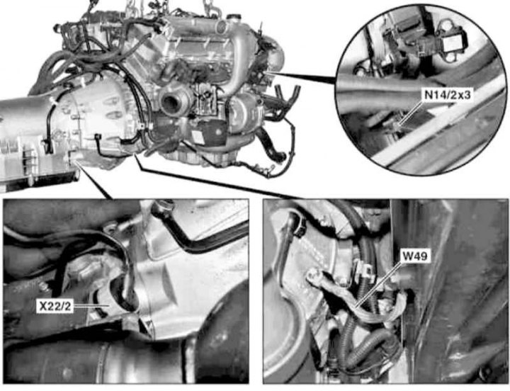
Layout of the main components of the electrical wiring of the M628 engine (2 of 2)
N14 / 2x3 - Outlet connector of circuit 30 of the preheating system
W49 - Transmission ground bus
X22 / 2 - Central automatic transmission connector
1. Disconnect the ground wire (W10) battery (see chapter Engine Electrical Systems).
2. Follow the procedures of paragraphs 3 to 6 (see above for M612).
3. Unlock and disconnect the connectors (5, 6 and 7) on the CDI control module (N39/2), - connector access (6) opens after disconnecting the connector (6).
4. Disconnect the connector (8).
5. Release the engine wiring harness (9) through the through hole in the body panel, - try not to damage the insulation.
6. Disconnect the ground bar (10).
7. Release the latch (11).
8. Unscrew the outlet connector of circuit 30 of the preheating system (N14/2x3).
9. After releasing the bayonet lock, disconnect the central electrical wiring connector (Х22/2) AT.
10. Unscrew the ground bus from the frame (W49) transmission.
11. Installation is carried out in the reverse order, - with the appropriate configuration (code ET2) deactivate the service mode of the TELE AID system (see Section Activation / deactivation of the service mode of the TELE AID emergency call system).
12. Finally, read the DTCs and clear the OBD memory using the STAR DIAGNOSIS scanner (6511 1801 00) (see chapter Engine Electrical Systems).
Removing the power unit
Note. All self-locking fasteners must be replaced without fail.
Petrol models
463.250/249 (G320/500 with M112.945/113.962 engines)
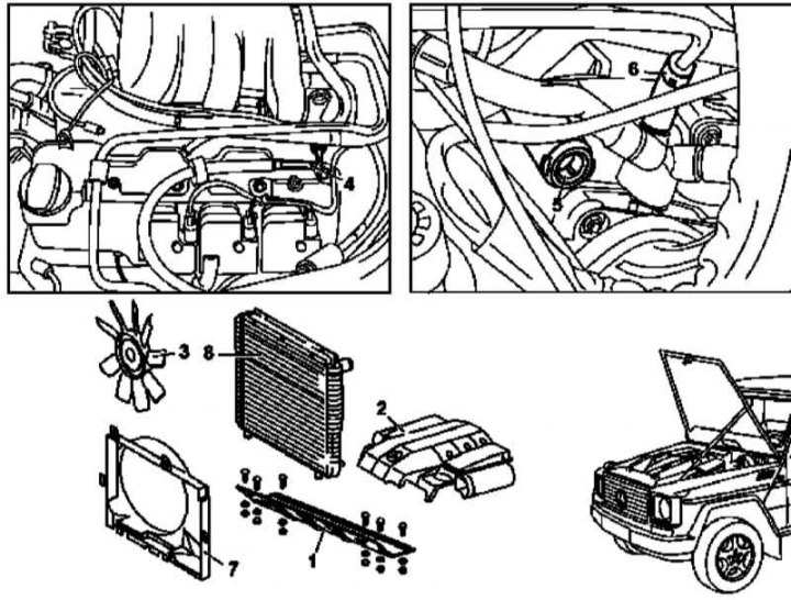
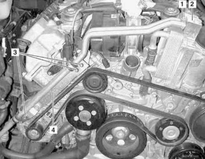
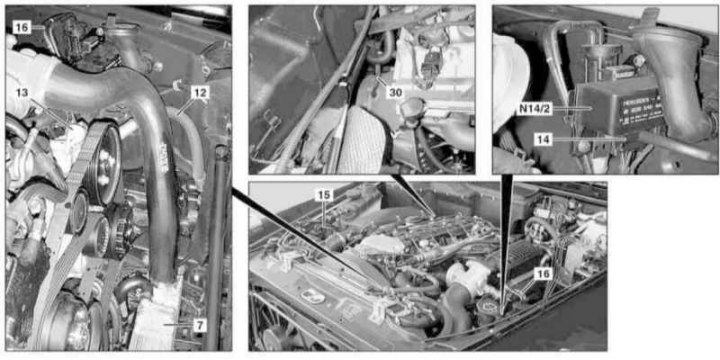
Preparing to remove the power unit on gasoline models (1 of 2)
Preparing to remove the power unit on gasoline models (2 of 2)
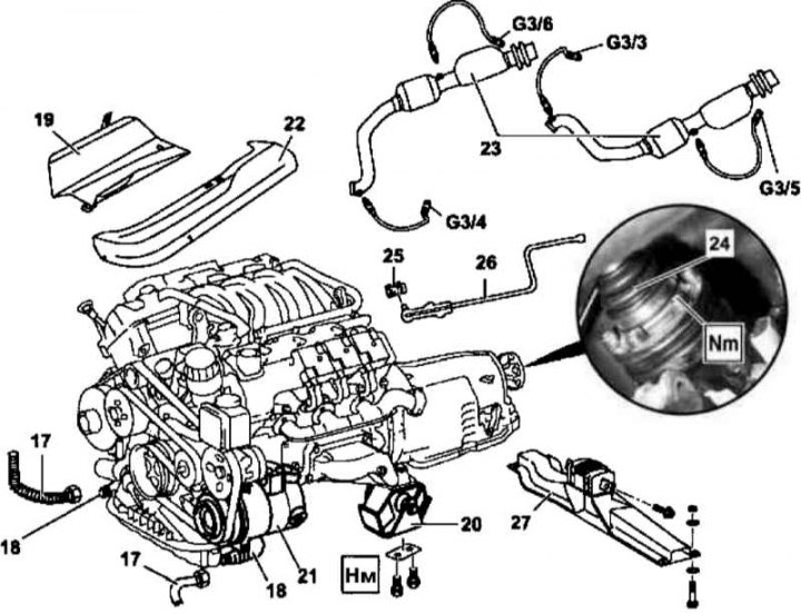
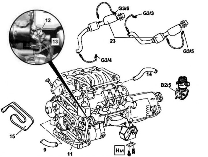
Details of installing the power unit on gasoline models
19 - Thermal protection screen; 22 - Heat shield; G3 / 3 - Left pre-catalytic lambda probe; G3 / 4 - Right pre-catalytic lambda probe; G3 / 3 - Left post-catalytic lambda probe; G3 / 4 - Right post-catalytic lambda probe
1. Put the car on a lift (see Section Jacking/hanging the car and transportation in case of an accident).
2. Remove the engine trim panel with built-in air cleaner (2), - lift the panel up and separate its cylinder head covers (see chapter Power supply and exhaust systems).
3. Disconnect the sleeves of the air intakes at the top of the wheel arches.
4. Disconnect the ground wire from the battery (see chapter Engine Electrical Systems).
5. Remove the bottom boot (1) engine compartment.
6. Empty the cooling system (see chapter Ongoing care and maintenance or Refrigeration, heating, ventilation and air conditioning systems).
7. Drain the engine oil (see chapter Ongoing care and maintenance).
8. Remove the viscous fan (3) and casing (7) fan assembly (see chapter Refrigeration, heating, ventilation and air conditioning systems).
9. Remove the cooling system radiator (see chapter Refrigeration, heating, ventilation and air conditioning systems).
10. Install the air conditioning radiator/condenser shield (metal or plastic sheet with dimensions of about 400x680x1 mm).
11. Disconnect the engine wiring (see above).
12. Disconnect the lines of the cooling path (9) from the water pump assembly.
13. Remove the hot-wire air mass sensor built into the intake duct (MAF) (B2/5) (see chapter Power supply and exhaust systems).
14. Disconnect the vacuum line (5) from the brake booster servo assembly at the rear of the intake manifold.
15. Disconnect the vacuum line (6) from the intake pipe.
16. Pump out the power steering fluid from the steering pump reservoir (11).
17. Disconnect from steering pump assembly (11) returnable (12) and pressure (13) hydraulic lines, - plug the open ends of the lines and fittings immediately with plugs prepared in advance.
18. Relieve pressure in the supply system through the service valve (see chapter Power supply and exhaust systems), then disconnect the fuel line from the fuel line (4), - get ready to collect poured fuel.
19. Remove the line of the cooling path (14).
20. Remove the accessory drive belt (15) (see Section Replacement of the auxiliary drive belt and elements of its tensioning mechanism), - to fix the tensioner, a rod with a diameter of 5 mm is required.
21. Disconnect the hoses (17) from oil pipelines (18), - Immediately seal the open ends of the lines with pre-prepared stoppers.
22. Remove the exhaust system assembly (see chapter Power supply and exhaust systems) (except models 463.249).
Note. If the engine is removed due to its failure, the catalytic converters (23) must be checked for the presence of chips, which must be removed before installation.
23. Unscrew the support from the frame (20) power unit suspensions.
24. Hang the unit by lifting it by the front lifting eye - make sure that no components are pinched.
25. Screw off the A/C compressor (21) from the timing cover and, without disconnecting the refrigeration lines, take it to the side.
26. Lower the power unit - again make sure that no components are pinched.
27. Unbolt the cardan shaft (24) from the transmission connecting flange, - the shaft mounting bolts must be replaced without fail.
28. Remove the clamp (25) and disconnect the shift rod from the transmission (26).
29. Remove the frame cross member (27) complete with rear transmission support (see Section Removal and installation of suspension mounts of the power unit) (except models 463.249).
30. Attach lifting straps to both eyelets on the power unit.
31. Lower the unit and pull it back out of the engine compartment.
32. Installation is carried out in the reverse order.
33. Check the unit for signs of developing coolant leaks.
Note. If the cylinder head gaskets have been replaced, the engine must first be warmed up to normal operating temperature.
34. Check the ATF level, if necessary, make the appropriate adjustment (see chapter Ongoing care and maintenance).
35. Start the engine and check it for signs of developing fluid leaks.
36. Finally, read the DTCs and clear the OBD memory using the STAR DIAGNOSIS scanner (6511 1801 00) (see chapter Engine Electrical Systems).
463.246 (G55 AMG with M113.982 engine)
1. Relevant illustrative material is provided in the illustrations Preparing to remove the power unit on gasoline models (1 of 2), Preparing to remove the power unit on petrol models (2 of 2), Details of the installation of the power unit on gasoline models, which include all references in the text.
2. Open the hood and lock it in an upright position.
3. Discharge the air conditioning system - contact a specialist.
4. Remove the engine trim panel with built-in air cleaner (2), - lift the panel up and separate its cylinder head covers (see chapter Power supply and exhaust systems).
5. Disconnect the sleeves of the air intakes at the top of the wheel arches.
6. Disconnect the ground wire from the battery (see chapter Engine Electrical Systems).
7. Remove the decorative grille (see chapter Body).
8. Remove the top forward cross beam.
9. Disconnect the communication lines and remove the auxiliary fan.
10. Disconnect the lines from the cooler of the A/C system, - immediately plug the open ends of the lines with pre-prepared plugs.
11. Remove the A/C cooler.
12. Remove the bottom boot (1) engine compartment (see resist. Illustration - Details of installation of the lower anther protection of the engine compartment on G55 AMG models).
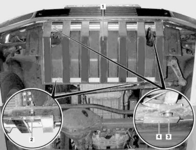
1 - duster
2, 3 — Screws
13. Empty the cooling system (see chapter Ongoing care and maintenance).
14. Drain the engine oil (see chapter Ongoing care and maintenance).
15. Disconnect the oil pipes from the oil-water heat exchanger (see resist. illustration - Details of fastening oil pipes to the oil-water heat exchanger of the compartment on G55 AMG models)
1 — Union connectors
2 - Heat exchanger
3 - Bolts
4 - support bracket
16. Follow the procedures of paragraphs 8, 9 and 11 to 19 for 463.250/249 (G320/500 with M112.945/113.9620 engines).
17. Remove the vacuum line from the inlet jumper to the purge valve.
18. Disconnect the refrigeration lines from the A/C compressor.
19. Disconnect the hoses (17) from oil pipelines (18), leading to the ATF cooler - immediately plug the open ends of the lines with stoppers prepared in advance.
20. Follow the procedures of paragraphs 22, 23, 27 and 28 for 463.250/249 (G320/500 with M112.945/113.9620 engines).
21. Turn out two bolts and remove a support of transmission from a crossbeam of a frame.
22. Attach slings to both eyelets on the power package.
23. Lift the front of the unit and remove it from the engine compartment.
24. Installation is carried out in the reverse order.
25. Prime the A/C system and check it for signs of leak development.
26. Continue as directed in paragraphs 33 to 36 for 463.250/249 (G320/500 with M112.945/113.9620 engines).
Diesel models
463.323 (G270 CDI with engine 612.965)
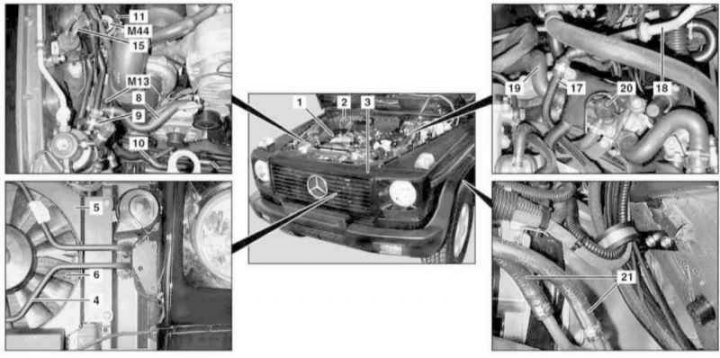
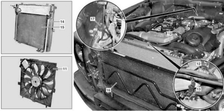
Preparation for the removal of the power unit on diesel models with the M612 engine (1 of 2)
Preparation for the removal of the power unit on diesel models with the M612 engine (2 of 2)
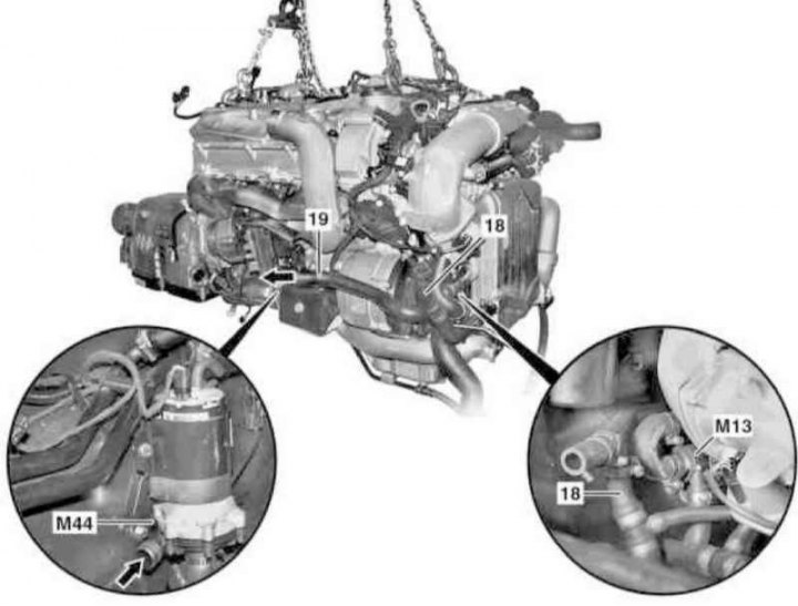
Details of the installation of the power unit on diesel models with the M612 engine
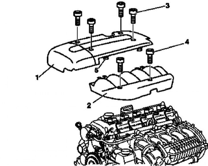
Details of the installation of trim panels for the cylinder head cover of the M612 engine
1 — The panel of finishing of a cover of a head of cylinders
2 — the panel of finishing of the air distributor
3, 4 - Mounting bolts
5 - Rubber pads
1. On models of the corresponding configuration (code ET2) activate the service mode of the TELE AID emergency call system (see Section Activation / deactivation of the service mode of the TELE AID emergency call system).
2. Disconnect the ground wire from the battery (see chapter Engine Electrical Systems).
3. Remove finishing panels from a cover of a head of cylinders.
4. Drive the car on a lift, or jack up the car and put it on stands (see Section Jacking/hanging the car and transportation in case of an accident).
5. Remove the lower anthers of an impellent compartment.
6. Empty the cooling system (see chapter Ongoing care and maintenance).
7. Remove the air cleaner (1) (see chapter Power supply and exhaust systems).
8. Remove the resonator chamber of the intake air path with the water collector (2) (see chapter Power supply and exhaust systems).
9. Remove primary catalytic converter (see chapter Power supply and exhaust systems).
10. Remove the viscous coupling of the cooling fan drive (see chapter Refrigeration, heating, ventilation and air conditioning systems).
11. Remove the radiator (see chapter Refrigeration, heating, ventilation and air conditioning systems).
12. On models equipped with A/C system (code H02) install air conditioning radiator/condenser shield (metal or plastic sheet with dimensions of about 400x680x1 mm).
13. Disconnect the line (4) power steering fluid cooling path.
14. On models equipped with A/C system (code H02) remove auxiliary cooling fan (5).
15. Remove the low temperature cooler (6) (see chapter Refrigeration, heating, ventilation and air conditioning systems).
16. Remove the intercooler (Intercooler) (7) turbocharging systems (see chapter Power supply and exhaust systems).
17. Disconnect the hoses (8 and 9) cooling path.
18. Give two nuts and, without disconnecting from the fitting connectors, separate the tube frame from the transverse pipe (10).
19. Remove the heat shield (11) circulation pump (M44) charge air cooling, then remove the actual pump assembly.
20. Remove the circulation pump (M13) coolant (see chapter Refrigeration, heating, ventilation and air conditioning systems).
21. Disconnect pressure line (12) from steering pump (13), - Prepare replacement O-rings for the hollow bolt of the in-line connector.
22. Disconnect the connector (14) at the outlet of the preheating system (N14/2).
23. Disconnect the right (15) and left (16) vacuum lines from the turbocharger and mixing chamber, respectively.
24. Disconnect the engine vacuum line (17) off line (18) brake booster servo.
25. Disconnect the engine wiring (see above).
26. Disconnect the line (19) cooling path from the fuel preheater (20).
27. Release the fuel lines (21) on the frame in the arch of the left front wheel.
28. Remove the speed sensor at the output of the transmission (B49), release the electrical wiring from the ATF filler support bracket, - prepare a replacement gasket and bandage.
29. Remove the latch (23) and disconnect the shift rod from the transmission (22).
Note. When installing a new traction, do not forget to adjust it (see chapter automatic transmission).
30. Attach lifting straps to both eyes of the power unit and hang the latter on the winch - make sure that no lines or components are pinched.
31. Appropriate models (code H02) disconnect the electrical wiring from the A/C compressor, then unscrew the compressor and take it aside without disconnecting the refrigeration lines.
32. Give fixing nuts (27) disconnect the propeller shaft (25) from connecting flange (26) transmission, - the nuts must be replaced without fail, - if necessary, loosen the fasteners and tilt the transmission slightly.
Note. When reinstalling the shaft, make sure it runs between the camshaft bearing flanges and the automatic transmission.
33. Lift the engine and remove it from the engine compartment through the top.
34. Support the transmission from below with a suitable jack - to remove the transverse beam with the rear suspension support of the power unit installed on it, the transmission will have to be raised.
35. Remove the rear suspension support of the power unit (see Section Removal and installation of suspension mounts of the power unit),
36. Remove the bolts (28 and 29) fastening the front suspension mounts of the power unit to the frame.
37. Remove the ATF cooling line support brackets from the right frame beam.
38. Disconnect the ventilation hose from the top of the AT crankcase - the engine will have to be slightly pulled forward.
39. Lower the rear part of the power unit and, moving it forward, remove it from the engine compartment - make sure that no suspension components and body panels are damaged.
40. Installation is carried out in the reverse order, - with the appropriate configuration (service mode code) deactivate TELE AID systems (see Section Activation / deactivation of the service mode of the TELE AID emergency call system).
41. Refuel and «pump» power steering system (see chapter Suspension and steering).
42. Bleed air from the cooling system (see chapter Ongoing care and maintenance).
43. Proceed further in accordance with the instructions given in paragraphs 33 to 36 for 463.250/249 (G320/500 with M112.945/113.9620 engines).
463.333 (G270 CDI with engine 628.962)
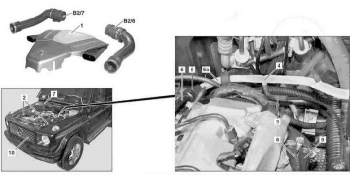
Preparation for the removal of the power unit on diesel models with the M628 engine (1 of 2)
Preparation for the removal of the power unit on diesel models with the M628 engine (2 of 2)
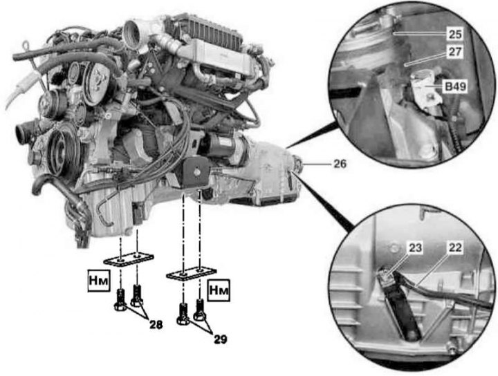
Details of the installation of the power unit on diesel models with the M628 engine (1 of 3)
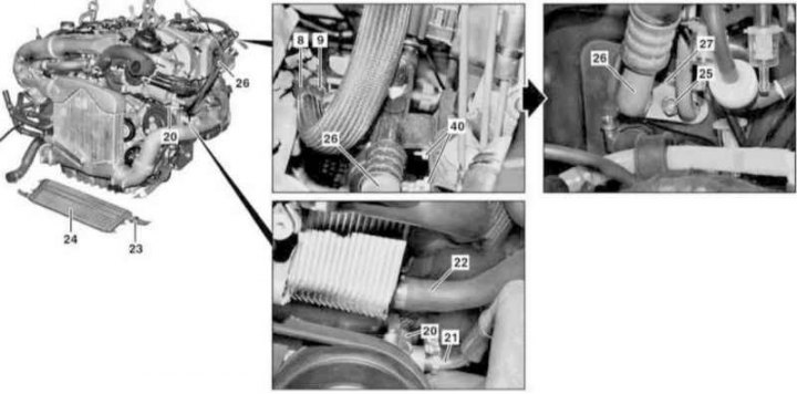
Details of the installation of the power unit on diesel models with the M628 engine (2 of 3)
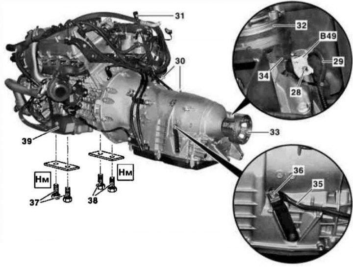
Details of the installation of the power unit on diesel models with the M628 engine (3 of 3)
1. Disconnect the ground wire from the battery (see chapter Engine Electrical Systems).
2. Open the hood and lock it in an upright position.
3. Remove the lower protection panels of the engine compartment.
4. Empty the cooling system (see chapter Refrigeration, heating, ventilation and air conditioning systems).
5. Remove the air cleaner (1) (see chapter Power supply and exhaust systems).
6. Remove the MAF sensors built into the left and right intake duct assemblies (B2/6 and B2/7) (see chapter Power supply and exhaust systems).
7. Remove intake ducts (2) from the mudguards of the left and right wings (see chapter Power supply and exhaust systems).
8. Disconnect from the tee (4) vacuum line (3) inlet shut off valve.
9. Squeezing the bar locks (5), disconnect the vacuum lines (6 and 6a).
10. Remove the resonator chamber of the intake air path with the water collector (7) (see chapter Power supply and exhaust systems).
11. Disconnect the engine wiring (see above).
12. Remove the front grill (10) (see chapter Body).
13. Remove the fan shroud (11) (see chapter Refrigeration, heating, ventilation and air conditioning systems).
14. Disconnect the vent lines (12 and 13) cooling path.
15. Remove the capacitor (14) complete with radiator (15) (see chapter Refrigeration, heating, ventilation and air conditioning systems).
16. Remove the low temperature cooler (16) (see chapter Refrigeration, heating, ventilation and air conditioning systems).
17. Disconnect cooling lines (17 and 18), - immediately seal the open ends of the lines with pre-prepared plugs.
18. Remove the circulation pump of the cooling system (M13).
19. Disconnect the cooling line (19) from charge air cooling circulation pump (M44).
20. Release the right hood cable.
21. Pump out the working fluid from the steering pump reservoir (20).
22. Disconnect from steering pump (20) /its pressure tank (21) and return (22), respectively, the lines - immediately plug the open ends of the lines and fittings with plugs prepared in advance.
23. Disconnect the ATF line (23) from transmission fluid cooler (24).
24. Loosen the nut (25).
25. Disconnect the inlet compressor line (26) from expansion valve (27) A/C systems, immediately plug the open ends of the lines and fittings with plugs prepared in advance, prepare replaceable sealing elements.
26. After pinching, disconnect the supply lines (9) and return (8) fuel - prepare to collect spilled fuel.
27. Remove the speed sensor at the output of the transmission (B49).
28. Separate the sensor assembly (B49) with rope (29) from the engine, - release the cable from the support plates (30) oil filler neck (31), remove the bandages.
29. Remove the exhaust system without the final muffler (see chapter Power supply and exhaust systems).
30. Unbolt the cardan shaft (32) from connecting flange (33) transmission, loosen the fasteners if necessary and tilt the transmission slightly.
Note. When reinstalling the shaft, make sure it runs between the camshaft bearing flanges and the automatic transmission.
31. Remove the latch (36) and disconnect the shift rod from the transmission (35).
Note. When installing a new traction, do not forget to adjust it (see chapter automatic transmission).
32. Connect lifting straps to both eyes of the power unit and hang the latter on the winch - make sure that no lines or components are pinched.
33. Support the transmission from below with a suitable jack and slightly raise it to remove the rear power unit suspension support.
34. Remove the rear suspension support of the power unit.
35. Remove the bolts (37 and 38) fastening to the frame, left (37) and right suspension mounts of the power unit.
36. Lower the rear of the unit and, having fed it forward, remove it from the engine compartment - make sure that no suspension components and body panels are damaged.
37. Installation is carried out in the reverse order.
38. Refuel and «pump» power steering system (see chapter Suspension and steering).
39. Proceed further as directed in paragraphs 33 to 36 for 463.250/249 (G320/500 with M112.945/113.9620 engines).