
VN 2.003
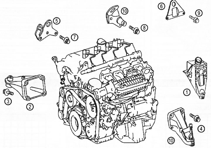
1. Left engine mount
2. Right engine mount
3. Screw M8x130 mm for fastening the left support to the cylinder block, strength class 8.8
4. Screw for fastening the support to the mounting block M8x40 mm
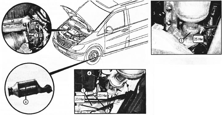
5. Front sling shackle
6. Rear sling shackle
7. Screw M8x20 mm for fastening the sling bracket to the cylinder head
8. Screw M7x20 mm for fastening the sling bracket to the cylinder head
9. M6x20 mm screw for fastening the rear sling bracket to the cylinder head
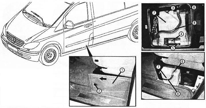
1. Disconnect the negative battery cable. To do this, follow the steps (pp. 1.1-1.6),
1.1. Remove the cover (1) at the base of the driver's seat.
1.2. Disconnect the ventilation hose (3) battery.
1.3. Remove bracket (4) battery.
1.4. Disconnect the negative battery cable (8) from battery (7).
VN 2.004
1. Lid
2. Clips
3. Ventilation hose
4. Battery bracket
5. Screws
6. Screw terminal "masses" on the battery
7. Battery (G1)
8. Negative battery wire (W10)
1.5. Install in reverse order.
1.6. Perform initial programming of the control system.
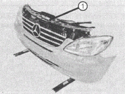
2. Remove the front panel (1). To do this, follow the steps (sq. 2.1-2.22).
VN 2.005
VN 2.006
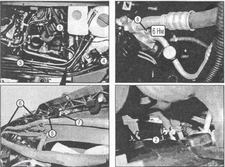
1. Oil return line
2. Oil lines
3. Front panel wiring harness
4. Quick connector
5. Bonnet lock cable
6. Brackets
7. Hood lock
8. Nut
VN 2.007
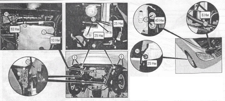
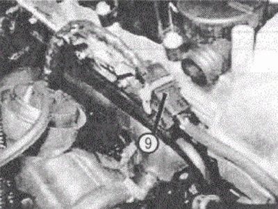
9. Expanding clip
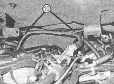
10. Compressed air piping
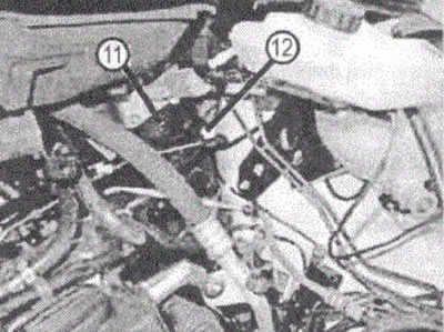
11. Supply pipe
12. Return flow tube
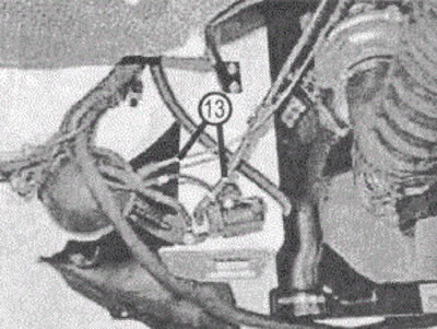
13, 14, 15, 16. Screws
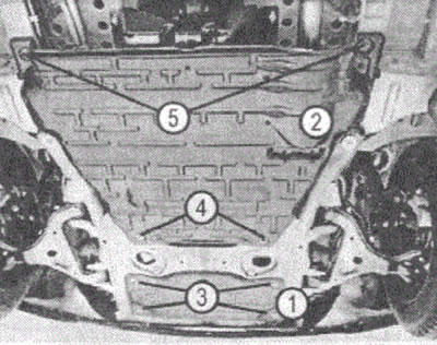
VN 2.008
1. Front of the protective tray of the engine compartment
2. Rear of the protective tray of the engine compartment
3. Screws (locks)
4. Screws
5. Nuts
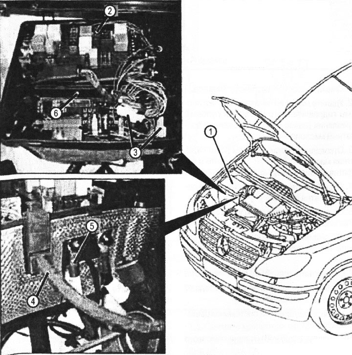
VN 2.009
1. Relay and fuse box
2, 3. Electrical connectors
4. Engine wiring harness
5. Positive terminal
6. Injection control unit
2.1. Remove the air filter housing.
2.2. Remove oil from the supply tank of the hydraulic power steering system (further - power steering), by disconnecting the oil return line (1).
2.3. Disconnect the oil lines (2) from the power steering system oil cooler Install plugs in the openings of the disconnected hoses.
2.4. Disconnect the coolant hose to remove the front block.
2.5. Unfasten harness fasteners (3) electrical wiring to the front unit.
2.6. Disconnect the quick connector (4) from the headlight washer and plug the connector.
2.7. Disconnect cable (5) opening the hood.
2.8. Disconnect the electrical wires from the top of the front unit.
2.9. Remove the refrigerant from the air conditioning system.
2.10. Unscrew the nut (8) from the high pressure line.
2.11. Remove-expanding clips (9).
2.12. Disconnect the forward protective pallet of a motor compartment.
2.13. Remove the air-to-air intercooler (intercoupler) with air ducts (10).
2.14. Disconnect the wiring harnesses from the bottom of the front panel.
2.15. Disconnect the supply tube (11) and return tube (12).
2.16. Loosen the screws (13).
2.17. Loosen the screws (14).
2.10. Loosen the screws (15).
2.19. Install the mounting tool on the front panel.
2.20. Spin the pints (16).
2.21. Remove the front panel.
2.22. Install the front panel in reverse order.
When installing, follow these steps.
- Fill the power steering system with oil and bleed air from the system.
- Check and correct the oil level in the automatic transmission.
- Adjust the position of the headlights.
- Check the correct operation of the headlight washer.
- Check the correct operation of the hood latch,
3. Remove the protective pallet of a motor compartment. To do this, follow the steps (pp. 3.1-3.2).
3.1. Remove the front (1) the protective tray of the engine compartment, for which follow these steps.
3.1.1. Loosen the screws (3) (for vehicles with a serial number in the VIN code up to 243 776) or open the locks (3) (for vehicles with serial number in the VIN code from 243 777).
3.1.2. Remove the front (1) protective tray of the engine compartment.
3.1.3. Install in reverse order.
3.2. Remove the back (2) protective tray of the engine compartment.
3.2.1. Loosen the screws (4) or open the locks (similar to paragraph 3.1.1).
3 2.3. Loosen the nuts (5).
3 2.4 Remove the back (2) protective tray of the engine compartment.
3.2.5. Install in reverse order.
4 Disconnect the electrical connectors and hoses by doing the following (sq. 4.1-4.35),
4.1. Remove the cover (1),
4.2. Disconnect the electrical connectors on the injection control unit (6).
4.3. Disconnect the electrical connector (2).
4.4. Disconnect electrical connectors (3)
4.5. Disconnect harness fasteners (4) engine wiring and move the harness to the side.
4.6. Disconnect the positive terminal (5), for which remove the protective cap and unscrew the nut
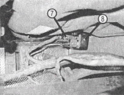
4.7. Disconnect the electrical connector (7) from the output stage of the preheating control unit (8).
VN 2.010
VN 2.011
4.9. Cut the plastic ties (10).
VN 2.012
4.10. Pressing the brake pedal repeatedly «use up» vacuum in a vacuum system.
4.11. Disconnect the vacuum hose (11) from the brake booster (12).
VN 2.013
4.12. Remove the vacuum tubes (13).
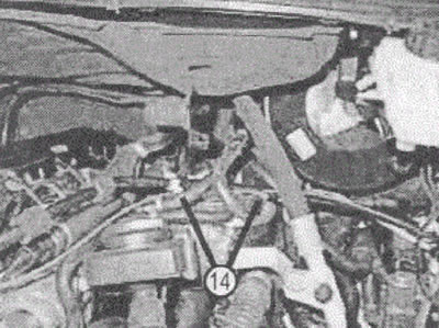
VN 2.014
4.13. Remove the fuel filter bracket front screws (only for engines 646.980/981).
4.14. Remove fuel return hoses (14) (only for engines 646.980/981).
4.15. For other engines - remove the fuel lines (14).
VN 2.015
4.16. Disconnect the hose (15) from thermostat housing (I6).
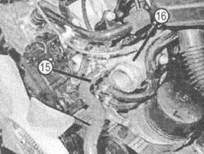
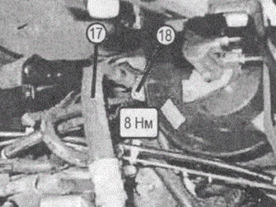
VN 2.016
4.17. unscrew the screw (18).
4.18. Disconnect the compressor hose (17).
4.19. Plug connections.
(pp. 4.17-4.19 only for vehicles with PR codes HH9 (adjustable air conditioner) and HH4 (automatic air conditioner).
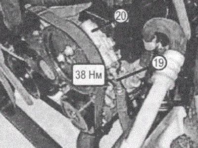
VN 2.017
4.20. Unscrew the power steering pressure hose connection (19) from power steering pump (20).
VN 2.018
VN 2.019
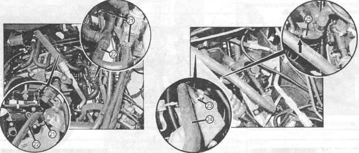
4.21. Loosen the clamps (21) (pic. VN 2.019).
4.22. Remove coolant hoses (22).
4.23. Loosen clamp (23)
4.24. Remove the hose (24).
4.25. Disconnect the hoses (25) (arrow).
(pp. 4.21 -4.25 - for cars with a serial number up to 113950).
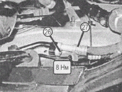
4.26. unscrew the screw (26) (pic. VN 2.020).
4.27. Disconnect the compressor tube (27),
4.28. Plug the pipes.
(pp. 4.26, 4.28 only for vehicles with PR codes HZ7 (adjustable air conditioner (Tempmatik) passenger compartment).
VN 2.020
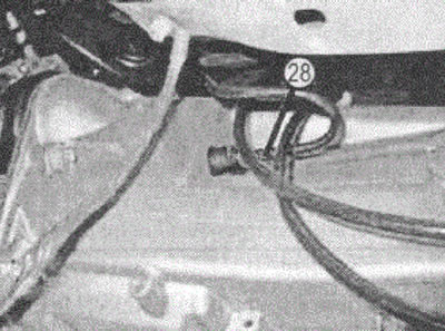
4.29. Disconnect the clutch hose (28) from the manual transmission.
4.30. Stop the hose.
VN 2.021
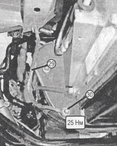
4.31. Disconnect the wire (29) «masses» from the power unit by unscrewing the screw (30).
VN 2.022
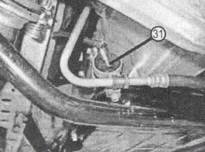
4.32. Disconnect the electrical connector (31) from the manual transmission.
VN 2.023
VN 2.024
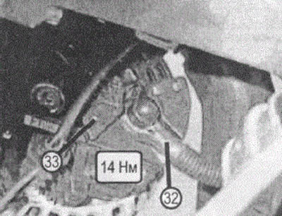
4.33. Disconnect the wire (32) from the generator (33) (pic. VN 2.024).
4.34. Connect in reverse order.
4.35. After connecting large wires, check the reliability of their fastening.
VN 2.025
Particulate filter. Shown for vehicles with code KA1
1. Exhaust pipe bracket
2. Bolts
3. Clamp
4. Primary exhaust gas converter
5. Collar
5. Disconnect the primary catalytic converter from the turbocharger flange, for which follow these steps (p.p. 5.1-5.6).
5.1. Disconnect the electrical connector (3) oxygen sensor (2) (pic. VN 2.025).
5.2. Remove catalytic converter 0G (6) (pic. VN 2.027).
VN 2.026
1. Air inlet
2. Oxygen sensor (G3/2)
3. Oxygen sensor connector
VN 2.027
1. Bolts
2. Flange connection
3. Rubber suspension of the exhaust pipe
4. Connector.
5. Exhaust pipe
6. Catalytic converter
VN 2.028
1. Electrical connector
2. Pressure hoses
3. Retainer
4. Rubber retainers
5. Collar
6. Particulate filter
5.3. Remove particulate filter (6) (pic. VN 2.028).
5.4. Remove the exhaust pipe bracket.
5.4.1. Loosen clamp (3) to the side (fig.VN 2.025).
5.4.2. Remove clamp (5) (pic. VN 2.025).
5.5. Remove the primary catalytic converter.
5.6. Install in reverse order.
Installation Notes
- Check that the elements of the exhaust system are correctly installed and that there are no impurities obstructing the passage of exhaust gases.
- Check the exhaust system for exhaust gas leaks while the engine is running.
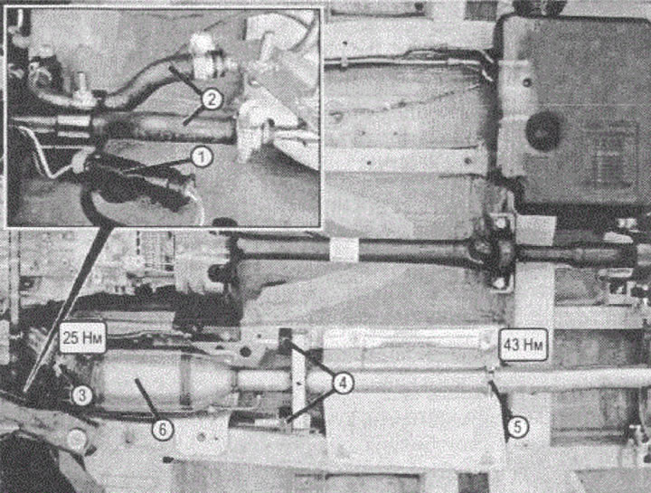
6. Install the CPR support device. To do this, follow the steps (pp. 6.1-6.6).
6.1. Install device (1) in place and secure with a bolt (2) (pic. VN 2.029).
6.2. Install the caliper (3) so that it touches the gearbox, and fix it with nuts (5).
6.3. Removing the device (1) do it in reverse order.
The actions described in paragraphs. 6.4-6.6 apply only to vehicles equipped with permanent all-wheel drive (PR number ZG2).
6.4. Install the support brace (4).
6.5. Move the spacer to the gearbox so that the spacer touches the body, and secure it with nuts (5).
6.6. Removing the spacer (4) do it in reverse order.
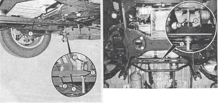
VN 2.029
1. CPR support device
2. Bolt
3. Caliper
4. Support brace
5. Nut
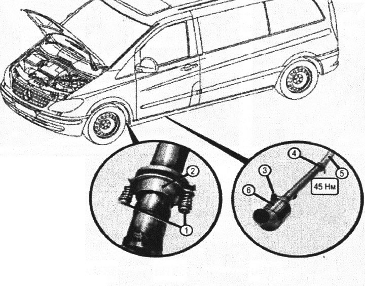
7. Remove the cardan shaft, for which follow these steps.
7.1.1. Disconnect the front section of the driveshaft from the transfer case (2) (only for vehicles with all-wheel drive (PR number ZG2).
7.1.2. Disconnect the front section of the driveshaft (1) from checkpoint (only for vehicles without all-wheel drive).
7.2. Disconnect the rear section of the driveshaft (1) from the main gear of the rear drive (3).
7.3. Remove the suspension bearing (4) front section of the propeller shaft.
7.4. Remove the suspension bearing (5) rear section of the propeller shaft.
Please note that the spacers for vehicles with and without all-wheel drive are different.
7.5 Remove cardan shaft (1). To do this, remove the safety bracket (b).
7.6. Check the universal joints for wear.
7.6.1. Apply extended life grease when reassembling (MB long-term grease) on the splined surfaces of cardan shafts.
7.6.2. Connect the front and rear sections of the propeller shaft.
VN 2.030
Shown for vehicles with code ZG2 Permanent front wheel drive 1. Driveshaft
2. Transfer box
3. Rear drive main gear
4. Front outboard propeller shaft bearing
5. Rear driveshaft support
6. Safety bracket
Attention: the marks on the connected sections of the drive shafts must be located as shown in fig. VN 2.031.
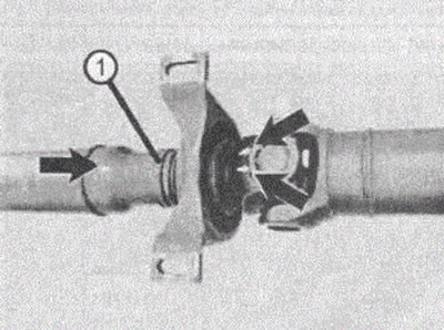
VN 2.031
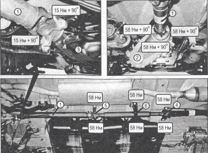
VN 2.032
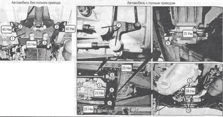
VN 2.033
1. Cross beam of a car without all-wheel drive
2, 3. Screws
4. The cross beam of a four-wheel drive car
5. Rear support of the power unit
6. Bracket
7. Spherical joints
8, 9, 10. Screws
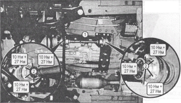
8. Remove the front axle drive shaft.
8.1. Disconnect the drive shaft (1) from the transfer case, having previously marked the relative position of the flange and the hinge.
8.2. Disconnect the drive shaft (1) from the main gear of the front axle.
8.3. Install in reverse order 9. Remove the cross beam.
10. Disconnect the manual transmission control cables (automatic transmission).
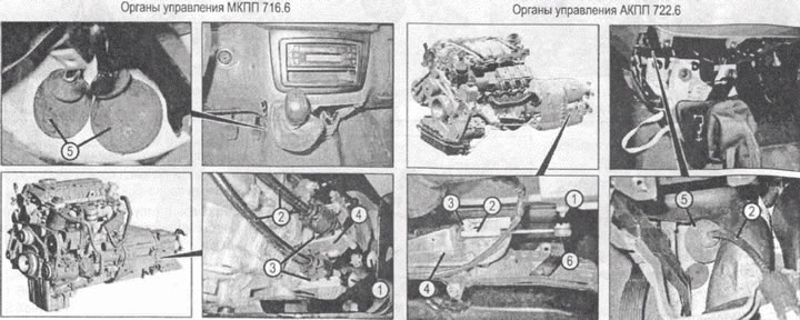
VN 2.034
1. Swivel ends of transmission control cables
2. Gearbox control cables
3. Fixing plastic
4. Bracket located on the checkpoint
5. Rubber boots
6. Spherical tips
11. Place the vehicle on a lifting platform.
12. Remove the oil separator.
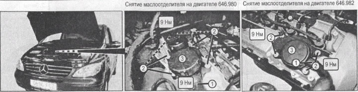
VN 2.035
1. Hose
2. Screws
3. Oil separator
13. Remove the power unit, for which follow these steps (pp. 13.1-13.9).
13.1. Remove the right engine mounting bolt.
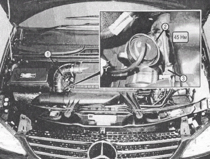
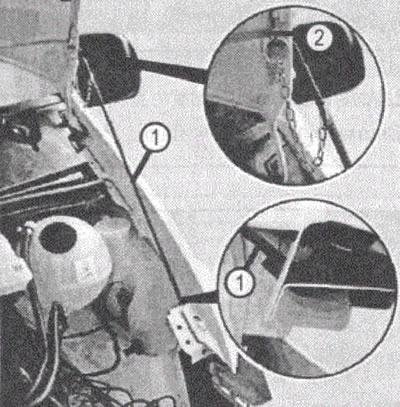
13.2. Secure the hood in the open position with a prop (1) with lock (2) (pic. VN 2.036).
13.3. Loosen nuts (3) and remove the bracket (4) (pic. VN 2.037),
13.4. Install the traverse (5) with attached bar (6) and fix it at the points (7).
13.5. Install the C-bracket.
13.6. Adjust the position of the center of gravity of the power unit with the nut (8).
VN 2.036
13.7. Loosen the screw on the left engine mount (9).
13.8. Lift the power unit and remove it from the engine compartment, if necessary, adjusting the position of the center of gravity with a nut (9).
13.9. Install the power unit in reverse order.
14. Install in reverse order.
15. Bleed the hydraulic clutch (for manual transmission 716.6), for which follow these steps (pp. 15.1-15.5).
15.1. Remove the plug (1) on the clutch housing. (pic. VN 2.038)
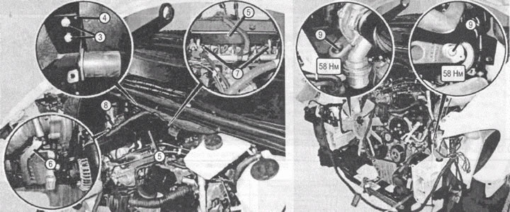
VN 2.037
3. Nuts
4. Bracket
5. Traverse
6. Rod
7. Rod attachment points
8. Nuts
9. Engine side mounting screws
15.2. Remove the cap on the coaxial clutch slave cylinder.
15.3. Unscrew the bleed valve with a socket wrench (2).
15.4. Bleed the air from the hydraulic system.
15.5. Screw the bleed valve, close it with a cap and install the plug (1).
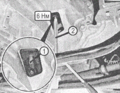
VN 2.038
1. Plug
2. socket wrench
16. Check the ease of movement of the gearbox control cables: the gear selection cable and the selected gear engagement cable. Adjust them if necessary.
17. Check up absence of leaks of technical liquids at the working engine.