
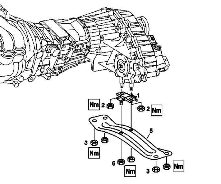
Installation details of the rear suspension support of the power unit (all models)
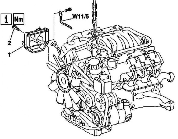
1. Installation details of the power unit rear mount on models equipped with a 111 series engine are shown in the illustration, to which all references in the text refer.
2. Support the engine.
3. Remove the rear powertrain landing cross member (5).
4. Remove the powertrain mount pad (1).
5. Installation is carried out in the reverse order.
Front supports
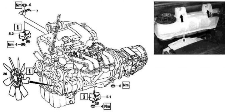
Installation details of the front suspension mounts of the power unit (models equipped with 111 series engine)
1. The installation details of the front suspension mounts of the power unit on models equipped with a 111 series engine are shown in the illustration, to which all references in the text refer.
2. Empty the cooling system (see chapter Ongoing care and maintenance).
3. Remove expansion tank (8) cooling systems.
4. Remove the viscous cooling fan assembly.
5. Turn out bolts of fastening of forward support (5.1 and 5.2) suspension of the power unit to the frame of the car.
6. Connect the winch to the engine.
7. Hang out the power unit and remove the pillows of the front supports (5.1 and 5.2).
8. Installation is carried out in the reverse order.
Note. The pillow of the left support is marked on the front side with a blue mark, the right one is green.
M112
Rear support
The design and location of the rear powertrain mount is the same as described above for models equipped with the 111 series engine.
Front supports
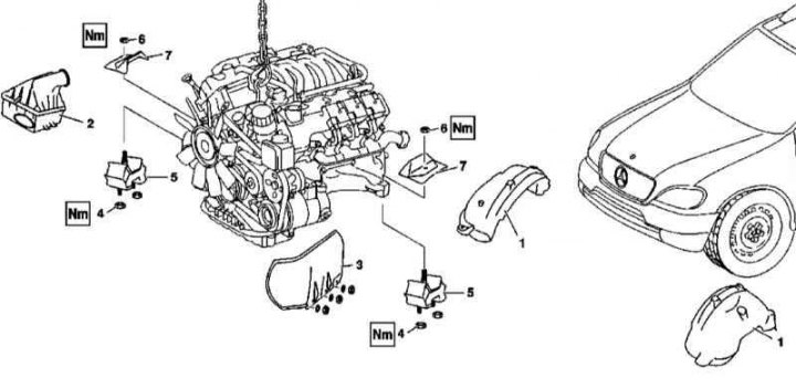
Installation details of the front suspension mounts of the power unit (models equipped with 112 series engines)
1. Installation details of the power unit front suspension mounts on models equipped with a 112 series engine are shown in the illustration, to which all references in the text refer.
2. Disconnect the negative cable from the battery.
3. Remove the wheel arch protectors (1).
4. Remove the engine cover.
5. Remove the air cleaner (2).
6. Remove the viscous cooling fan assembly.
7. Remove the heat shield (3) fuse-relay mounting block.
8. Give nuts (4) support fastenings (5).
9. Connect the winch to the engine.
10. Give nuts (6) and remove the protective screens of the support pads (7).
11. Hang the engine and remove the support cushions (5).
12. Installation is carried out in the reverse order.
Left side support
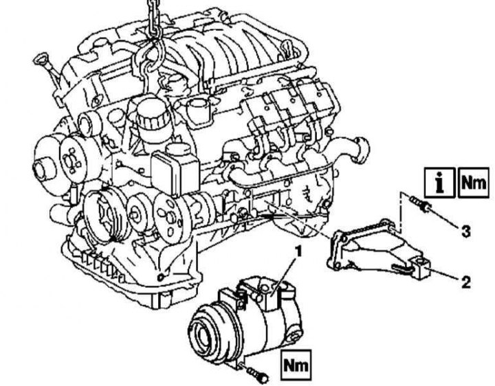
Details of the installation of the left side suspension support of the power unit (models equipped with 112 series engines)
1 - K / V compressor
2 — Support of the power unit
3 - Bolt
1. The installation details of the left side support of the suspension of the power unit on models equipped with a 112 series engine are shown in the illustration, which includes all references in the text.
2. Remove the front engine mounts (see above).
3. Remove the accessory drive belt (see chapter Engine).
4. Remove the A/C compressor (1).
5. Unscrew the left support (2) from the engine crankcase and remove it from the vehicle.
6. Installation is carried out in the reverse order.
Right side support
Details of installation of the right lateral support of a suspension bracket of the power unit (models equipped with 112 series engines)
1 — Support of the power unit
2 - Bolts
W11 / 5 - Ground bus engine / body
1. The installation details of the right side support of the suspension of the power unit on models equipped with a 112 series engine are shown in the illustration, which includes all references in the text.
2. Remove the front engine mounts (see above).
3. Unbolt the W11/5 earth bar from the motor.
4. Unscrew the right support (1) from the engine crankcase and remove it from the vehicle.
5. Installation is carried out in the reverse order.
M113
Rear support
The design and location of the rear powertrain mount is the same as described above for models equipped with the 111 series engine.
Front and side supports
Installation details of the front suspension mounts of the power unit (models equipped with 113 series engines)
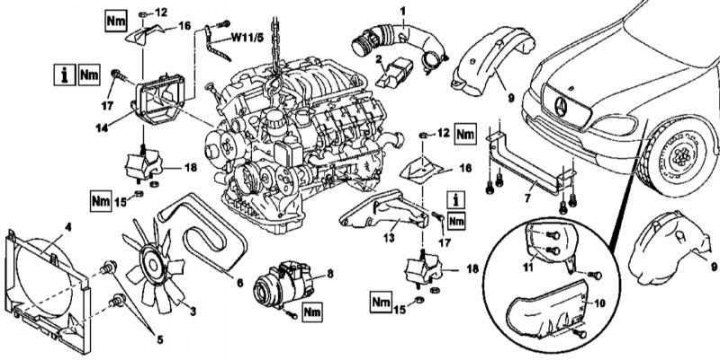
1 - Connecting sleeve; 2 - Resonator; 3 - Assembly of a fan with a viscous coupling; 4 - Fan casing; 5 - Bolts for fastening the fan casing; 6 - Auxiliary drive belt; 7 - Air baffle; 8 - A/C compressor; 9 - Lockers; 10 - Deflectors; 11 - Thermal protection screen; 12 - Nuts; 13 - Left side support; 14 - Right side support; 15 - Nuts; 16 - Protective screens of pillows; 17 - Mounting bolts; 18 - Pillows of the front supports; W11 / 5 - Grounding bus engine / body
1. The installation details of the front and side suspension mounts of the power unit on models equipped with a 113 series engine are shown in the illustration, to which all references in the text refer.
2. The execution procedure is almost identical to that described above for models equipped with 112 series engines.