
Checking the basic position of the balancing shaft (112 series engines)
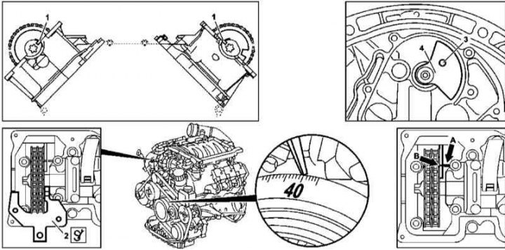
1. Illustrative material for checking the basic position of the balancing shaft on 112 series engines is presented in the illustration, which includes all references in the text.
2. Remove the transmission assembly (see chapter automatic transmission).
3. Remove the drive disk (see Section Removal and installation of a flywheel/drive disk).
4. Remove cylinder head covers.
5. On engines equipped with an air pump, remove the right combination valve.
Note. The sealing gasket of the combination valve must be replaced without fail.
6. Turn the engine to position 40°after TDC of the piston of the first cylinder.
7. Check the basic position of the camshafts (see Section Setting the basic position of the camshafts).
8. Install locking plates (2) on the right and left cylinder heads, filling them into the grooves (1) camshafts.
9. If the balance shaft is properly installed, the hole (3) in the rear counterweight (4) must be aligned with the socket in the engine crankcase, - insert a pin with a diameter of 8.40 ÷ 8.55 mm into the holes. Make sure also to balance the risks (IN) on front counterweight with pin (A) in the crankcase, - the risk and pin are located approximately 22 cm below the mating surface of the head and are viewed through a window in the left timing cover.
10. If the basic setting is violated, the balancing shaft must be replaced.
11. Reinstall all removed components in reverse order of removal.