



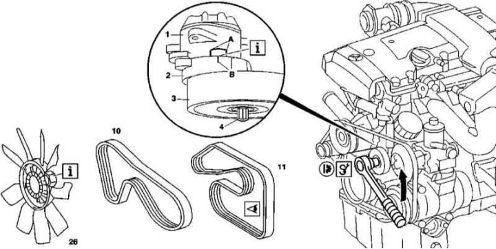
Accessory Drive Belt Installation Details on Models Equipped with 111 Series Engine
1. The accessory drive belt installation details on models equipped with the 111 series engine are shown in the illustration to which all references in the text refer.
2. If equipped, remove the cooling fan viscous coupling (26) - the fastener has a left-hand thread. On models with an electric fan, remove the fan assembly (see Chapter Cooling, heating and air conditioning systems).
3. If equipped, remove the V-belt (10) of the A/C compressor drive.
4. Turn the tensioner lever (2) with the roller (3) counterclockwise on the stud (4), loosen the tension of the accessory drive belt (11).
Note: Do not turn the lever on the tensioner roller nut.
5. Remove the belt (11) and assess its condition (see Chapter Replacement of the auxiliary drive belt and elements of its tensioning mechanism). Replace if necessary.
6. Installation is carried out in the reverse order - ensure that the components of the automatic tension adjustment mechanism (A and B) are correctly positioned.
Tensioner damper
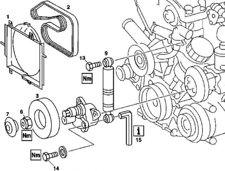
Installation details of the automatic tensioner damper for the accessory drive belt on models equipped with a 111 series engine
6 - Nut; 7 - End cap (models produced up to 03.09); 13 - Bolt M8x35 with washer; 14 - Bolt M8x25 with washer
1. Installation details of the accessory drive belt tensioner damper on models equipped with a 111 series engine are shown in the illustration to which all references in the text refer.
2. Remove the cooling system fan shroud (1) (see Chapter Cooling, heating and air conditioning systems).
3. Remove the drive belt (2).
4. Unbolt and remove the tension roller (3).
5. Loosen the mounting bolt using the wrench (15) and remove the tensioner damper (9).
6. Installation is carried out in reverse order.
Tensioner
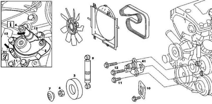
Installation details of the automatic accessory drive belt tensioner on models equipped with a 111 series engine
1. Installation details of the accessory drive belt tensioner on models equipped with the 111 series engine are shown in the illustration to which all references in the text refer.
2. Remove the tensioner damper (9) (see above).
3. On models with K/V, unbolt the support bracket (10).
4. Turn the tensioner lever on the stud (4) counterclockwise and secure it with the rod (01) inserted into the special receiving hole (arrow), thereby providing access to the upper mounting bolt (12).
5. Unbolt the tensioner (41) and remove it from the engine.
6. Installation is carried out in reverse order.
M112/113
Belt
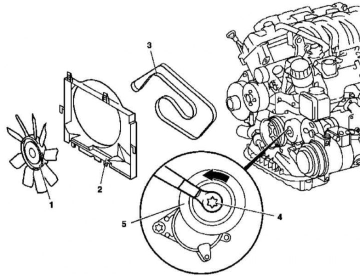
Accessory Drive Belt Installation Details on Models Equipped with 112 and 113 Series Engines (except for the ML 55 AMG and ML 500 models)
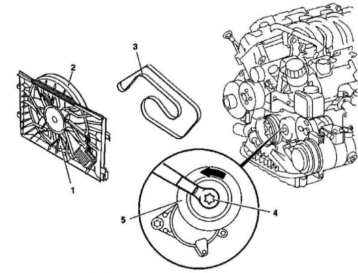
Accessory Drive Belt Installation Details on Models Equipped with 112 and 113 Series Engines (models ML 55 AMG and ML 500)
1. The details of the accessory drive belt installation on models equipped with 112 and 113 series engines are shown in the illustrations to which all references in the text refer.
2. Remove the fan assembly (1 and 2) (proceed according to the package) (See Chapter Cooling, heating and air conditioning systems).
3. Turn the pin (4) of the tension roller (5) counterclockwise, loosen the belt (3) and lock the roller using a 5 mm diameter rod.
4. Remove the belt and carefully examine its condition (see Chapter Replacement of the auxiliary drive belt and elements of its tensioning mechanism). Replace if necessary.
5. Installation is carried out in reverse order.
Tensioner
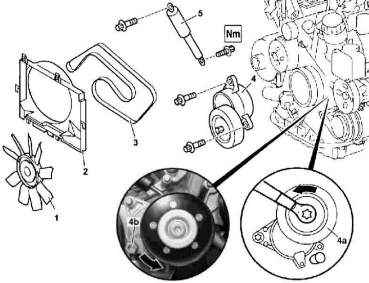
Installation details of the automatic tensioner of the auxiliary drive belt on models equipped with 112 and 113 series engines
1. Installation details of the accessory drive belt tensioner on models equipped with 112 and 113 series engines are shown in the illustration to which all references in the text refer.
2. Remove the drive belt (3) (see above).
3. Turn the tension roller (4a) counterclockwise and secure it with a 5 mm diameter rod.
4. After unscrewing the self-locking bolt (4b), remove the tensioner (4) from the timing belt drive cover.
5. Installation is carried out in reverse order.
M612
Belt
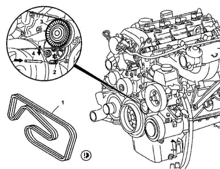
Accessory Drive Belt Installation Details for Models Equipped with 612 Series Engine
1 - Drive belt; 2 - Tensioner; 3 - Tension roller; 4 - Pin
1. Accessory drive belt installation details on models equipped with a 612 Series engine are shown in the illustration to which all references in the text refer.
2. Remove the fan assembly and its shroud (see Chapter Cooling, heating and air conditioning systems).
3. Turn the tensioner and lock it with the pin (4), loosen and then remove the drive belt (1).
4. Examine the condition of the belt (see Chapter Replacement of the auxiliary drive belt and elements of its tensioning mechanism), replace it if necessary.
5. Installation is carried out in reverse order.
M628
Belt
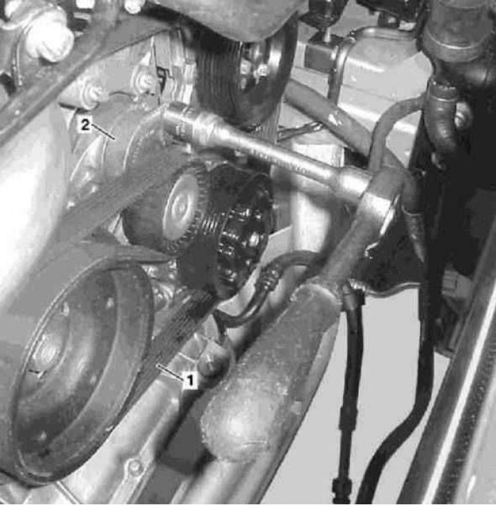
Accessory Drive Belt Installation Details for Models Equipped with 628 Series Engine
1 - Drive belt; 2 - Tensioner
1. Accessory drive belt installation details on 628 Series engine equipped models are shown in the illustration to which all references in the text refer.
2. Jack up the car and place it on supports.
3. Remove the lower section of sound insulation.
4. Disconnect the air hose from the lower air duct.
5. Loosen the belt (1) and remove it from the engine.
6. Examine the condition of the belt (see Chapter Replacement of the auxiliary drive belt and elements of its tensioning mechanism), replace it if necessary.
7. Installation is carried out in reverse order.
Tensioner
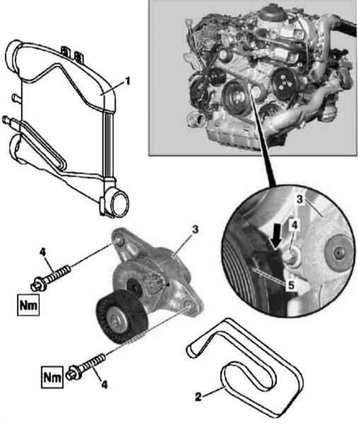
Installation details of the automatic accessory drive belt tensioner on models equipped with a 628 series engine
1. Installation details of the accessory drive belt tensioner on models equipped with the 628 series engine are shown in the illustration to which all references in the text refer.
2. Remove the drive belt (2) (see above).
3. While turning the engine in the normal direction, unscrew the screws (4) and remove the tensioner (3).
4. Installation is carried out in reverse order.