
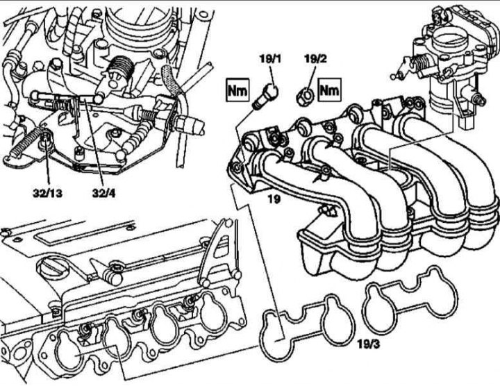
111 Series Engine Intake Pipe Installation Details
19 - Inlet pipeline; 19/1 - Mounting bolt; 19/2 - Fastening nuts; 19/3 - Sealing gaskets; 32/4 - Connecting rod; 32/13 - Bolt
M111
1. Details of the installation of the intake manifold of the 111 series engine are shown in the illustration, to which all references in the text refer.
2. Disconnect the negative cable from the battery.
3. Remove the air cleaner bypass pipe.
4. Disconnect the vacuum and electrical lines.
5. Remove the fuel line assembly with injectors (see chapter Removal and installation of the fuel distributive highway and injectors).
6. Release from intermediate clamps on the inlet pipeline an electroconducting of the engine.
7. Disconnect the wiring from the crankshaft position sensors (CKP) and detonation (KS).
8. Disconnect circuit 50 from the starter.
9. Remove the idle speed stabilization system actuator (ISC).
10. Separate the throttle cable from the intake manifold.
11. Loosen the mounting bolts (19/1) and nuts (19/2) and remove the intake manifold assembly (19).
12. Installation is carried out in the reverse order.
13. Finally, check that the idle speed is set correctly and that the throttle actuator is functioning properly.
M112/113
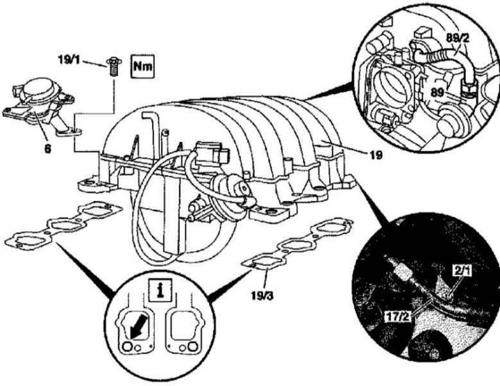
112 and 113 series intake manifold installation details
Arrow - Hole for installing a combination valve
1. Details of installation of the inlet pipeline of engines of the 112 and 113 series are shown in the illustration, to which all references in the text refer.
2. On models equipped with an electronic ignition switch (EIS), remove the key from the ignition switch.
3. Remove the cylinder head cover/air cleaner.
4. Remove the intake air path assembly with the air mass sensor (MAF).
5. Disconnect the supply line from the fuel distributor (17/2).
6. Remove the fuel line assembly with injectors (see chapter Removal and installation of the fuel distributive highway and injectors).
7. Turn out bolts (2/1) fixing the cylinder head cover.
8. Disconnect from the inlet pipeline (19) vacuum lines.
9. Disunite electric sockets.
10. Loosen the union nut and disconnect the line (89/2) from the valve (89) exhaust gas recirculation systems (EGR).
11. Remove the bolt (19/1) and remove the combination valve assembly (6).
12. Remove the inlet pipeline (19).
13. Installation is carried out in the reverse order.