
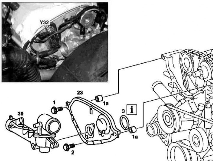
Details of installation of a forward cover of a head of cylinders (111 series engines)
1. Details of installation of the front cover of the cylinder head of the 111 series engine are shown in the illustration, to which all references in the text refer.
2. Remove the cylinder head (see Section Removing and installing the head (OK) cylinders).
3. Remove the thermostat cover (3) (see chapter Cooling, heating and air conditioning systems).
4. Unbolt the secondary air mixing valve (Y32).
5. Turn out fixing bolts (1 and 2) and remove the front cylinder head cover.
6. Thoroughly clean the mating surfaces. Installation is carried out in the reverse order - the cover is planted on the sealant. Make sure all fasteners are tightened to the correct torque.
Timing cover M111
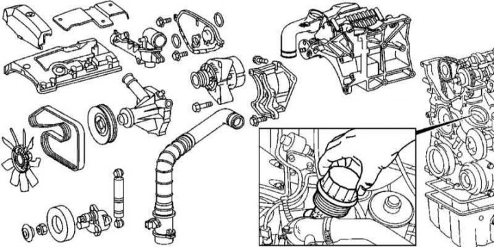
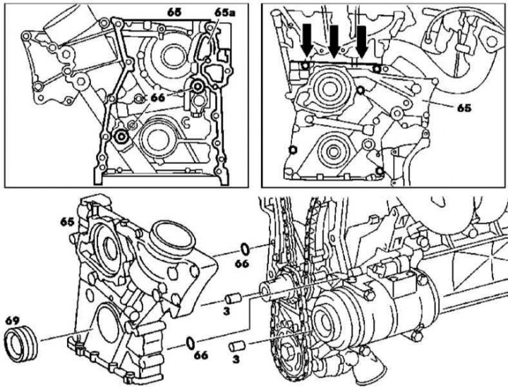
Timing cover installation details on 111 series engines
Timing cover installation details on 111 series engines
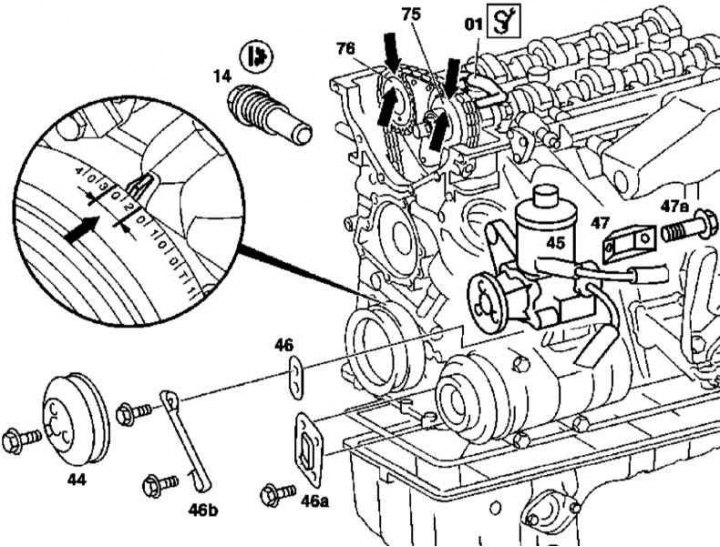
Timing cover installation details on 111 series engines
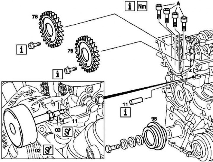
A - Bolts for fastening the timing cover to the cylinder head
Timing cover installation details on 111 series engines
3 - Guide pins
1. The details of installing the timing cover on the 111 series engine are shown in the illustrations, which include all references in the text.
2. Disconnect the negative cable from the battery.
3. Remove the assembly of the left sleeve of the air boost path with the MAF sensor (see Section Removal and installation of the engine).
4. Remove the oil filter cartridge (see chapter Changing the engine oil and oil filter) and drain the oil into a prepared container.
5. Remove the viscous cooling fan assembly (see chapter Cooling, heating and air conditioning systems).
6. Remove the cooling fan shroud (see chapter Cooling, heating and air conditioning systems).
7. Remove the oil pan (see Section Maintenance of the lubrication system).
8. Remove the blower drive belt.
9. Remove the accessory drive belt.
10. Empty the cooling system (see chapter Cooling, heating and air conditioning systems).
11. Remove generator support bracket/generator assembly with support bracket (see chapter Engine Electrical Systems).
12. Remove the accessory drive belt tensioner assembly (see chapter Engine).
13. Remove the front cylinder head cover (see above).
14. Remove the water pump (see chapter Cooling, heating and air conditioning systems).
15. Remove the steering pump drive pulley (44), - keeping the pulley from turning can be done by crimping the temporarily installed drive belt.
16. Unbolt the bracket (47).
17. On models without A/C, remove the bracket (46b). On models with A/C, remove the brackets (46) And (46a).
18. Remove the steering pump (45) and move it aside without disconnecting the hydraulic lines.
19. Turning the crankshaft in the normal direction, bring the piston of the first cylinder to a position of 20-30°after TDC (see arrows in illustration 5.7b).
20. Using locking rods (01) fix the camshafts.
21. Mark the position of the gas distribution chain relative to the camshaft sprockets with a marker (75 and 76).
22. Remove chain tensioner (14).
23. Remove Prom Stars (76) and inlet (75) camshafts.
Note. The sprocket mounting bolts must be replaced without fail.
24. Remove the intake shaft assembly with the regulator.
25. Remove the chain guide pins (11).
Note. During installation, the pins are seated on the sealant.
26. Remove the bolts (A) fastening the timing cover to the cylinder head.
Note. The bolts are equipped with TORX heads.
27. Remove the drive belt pulley assembly with built-in vibration damper (95).
28. Mark the timing cover bolts with a marker.
29. Turn out fixing bolts and remove a cover (65), - take care not to damage the head gasket.
30. Replace front crankshaft oil seal (see Section Replacing the front crankshaft oil seal).
31. Thoroughly clean the mating surfaces of the cover and crankcase.
32. Replace o-rings (66).
33. Lubricate the mating surface of the cover with sealant, making sure that the latter does not get into the oil reservoir (65a) gas distribution chain.
34. Installation is carried out in the reverse order - when installing the cover, pull the chain up, completely removing its slack in the lower part. Make sure all fasteners are tightened to the correct torque.
M112/113
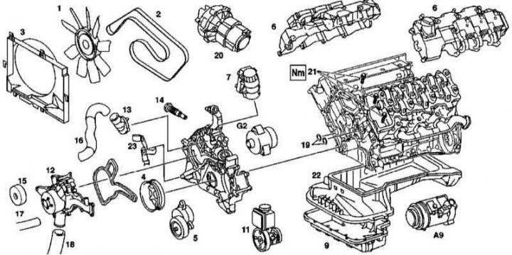
Timing cover installation details on 112 and 113 series engines
1 - Assembly of a fan with a viscous coupling; 2 - Auxiliary drive belt; 3 - The casing of the fan of the cooling system; 4 - Torsional vibration damper; 5 - Assembling the tensioner; 6 - Cylinder head covers with ignition coils; 7 - Oil filter housing with built-in liquid heat exchanger; 9 - Lower section of the oil pan; 11 - Steering pump; 12 - Water pump; 13 - Thermostat casing; 14 - Timing chain tensioner; 15 - Guide roller; 16 - Hose of the cooling path from the radiator to the thermostat housing; 17 - Hose of the cooling path connecting the circulation and water pumps (additional equipment); 18 - Hose of the cooling path from the radiator to the water pump; 19 - Sealing rings of the timing case; 20 - Air pump; 21 - Bolts for fastening the timing cover to the cylinder head; 22 - Upper section of the oil pan; 23 - Support bracket for oil pipelines АТ; A9 - A/C compressor; G2 - Generator
1. The details of installing the timing cover on 112 and 113 series engines are shown in the illustration, which includes all references in the text.
2. Disconnect the negative cable from the battery.
3. Remove powertrain trim panels.
4. Drain the coolant from the radiator.
5. Remove the power unit cover/air cleaner assembly from the cylinder heads.
6. Remove the viscous cooling fan assembly (1).
7. Turn out the lower bolts and remove a casing of the fan/assembly of the electric fan.
8. Install the A/C radiator/condenser shield.
9. Remove the accessory drive belt (2).
10. Remove cylinder head covers (6).
11. Disconnect the lines (17 and 18) water pump.
12. Disconnect the hose (16) from the thermostat housing.
13. Remove and, without disconnecting the refrigeration lines, take aside the A/C compressor (A9).
14. Remove the lower section of the oil pan (see Section Maintenance of the lubrication system).
15. Remove the upper section of the oil pan (see Section Maintenance of the lubrication system).
16. Remove the accessory drive belt tensioner assembly.
17. Remove the vibration damper (4)
18. Remove the timing chain tensioner (14).
19. Remove the oil filter housing equipped with a built-in liquid heat exchanger (7).
20. Remove and, without disconnecting the hydraulic lines, slide the steering pump assembly to the side (11).
21. Remove the guide roller from the timing cover (15) accessory drive belt.
22. Remove the air pump (20).
23. Separate electroconducting from the thermostat.
24. Remove the bolts (21) fastening the timing cover to the cylinder heads.
25. Turn out screws of fastening of a cover of a drive of GRM.
Note. When installing, the threaded part of the screws should be lubricated with sealant.
26. Remove the timing cover.
27. Thoroughly clean the mating surfaces of the cover and crankcase.
28. Installation is carried out in the reverse order - a cushion of sealant with a width of about 2.0 mm and a thickness of about 0.5 mm should be applied to the mating surface of the cover (make sure that the sealant does not get into the oil channels). Don't forget to replace the cover o-rings (19) and front crankshaft seal. Make sure all fasteners are tightened to the correct torque.
29. Finally, clear the memory of the on-board self-diagnosis system by first reading the DTCs stored in it (see chapter Engine Electrical Systems).