
On the example of model 463.323 (M612 engine)
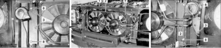
Auxiliary Fan Assembly Installation Details on Models 463.323 (1 of 2)
1 - Upper transverse bulkhead; 2 - Power steering fluid cooling coil; 3 - Bolts; 5 - Auxiliary fan assembly; 8 - Nuts
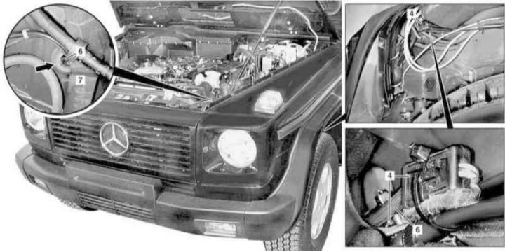
Auxiliary Fan Assembly Installation Details on Models 463.323 (2 of 2)
4 - Wiring connector; 6 - Wiring of auxiliary fans; 7 - Wheel arch trim panel
1. On models of the corresponding configuration (code ET2) activate the service mode of the TELE AID emergency call system (see Section Activation / deactivation of the service mode of the TELE AID emergency call system).
2. Turn on the auxiliary and connect it to the original battery, then disconnect the negative cable from the battery.
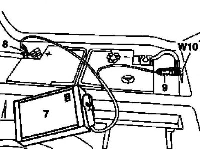
7 - Auxiliary battery
8 - Module positive wire terminal
9 - Terminal of the negative wire of the module
W10 - Battery Ground
3. Remove the front grille (see chapter Body).
4. Remove the upper front cross member of the frame (1) and take it aside assembled with the hood fixing lock.
5. Turn out fixing bolts (3) from the coil (2) power steering fluid cooling.
6. Remove trim panel (locker) left front wheel arches (7).
7. Disconnect the connector (4) auxiliary fan assembly (5), when assembling, do not forget to replace the bandage bands.
8. Push the wiring (6) auxiliary fan assembly (5) into the hole (arrow) in the locker (7).
9. Give nuts (8) and by pulling up and pushing the coil to the side (2) power steering cooling, remove the auxiliary fan assembly (5).
10. Installation is carried out in the reverse order. On models of the corresponding configuration, do not forget to deactivate the service mode of the TELE AID system (see section see section Activation / deactivation of the service mode of the TELE AID emergency call system).
11. In conclusion, clear the memory of the processor of the on-board self-diagnosis system (see chapter Engine Electrical Systems).