



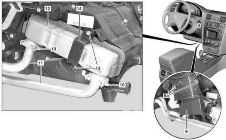
Heater heat exchanger installation details
9 - Nozzle; 9a - Spring clamps; 10 - Connecting clamps; 11 - Cooling tract tubes; 12 - Heat exchanger; 13 - TORX head bolts; 14 - Clamp
1. After releasing the pressure in the tract, empty the cooling system (see Chapter Routine care and maintenance).
2. On models with the corresponding configuration (code ET2), activate the service mode of the TELE AID emergency call system (see Section Activation/deactivation of the service mode of the TELE AID emergency call system).
3. Disconnect the negative battery cable - there is no need to connect an auxiliary battery.
4. Remove the instrument panel (see Chapter Body).
5. Remove the gas pedal.
6. Remove the floor carpet in the left rear footwell (see Chapter Body).
7. Remove the cover from the left side of the front center tunnel.
8. Remove the air supply hose to the left rear footwell.
9. Release the spring clamps (9a) and remove the attachment (9).
10. Remove the connecting clamps (10) and disconnect the cooling tract tubes (11) from the heat exchanger (12); the clamps (10) and sealing rings must be replaced.
11. Remove the bolts (13).
12. Remove the clamp (14) and take out the heat exchanger (12).
13. Thoroughly clean the inside of the heat exchanger casing, completely removing traces of coolant leaks, which are the source of unpleasant odors.
14. Installation is carried out in reverse order.
15. On models with the corresponding configuration, deactivate the service mode of the TELE AID system.
16. Finally, clear the memory of the on-board diagnostic system processor (see Chapter Engine electrical systems).