
Attention! Self-locking fasteners must be replaced without fail!
Dashboard Installation Details (1 of 12)
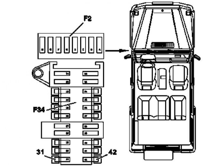
31 - Fuse EIS / EZS; 42 - Instrument cluster fuse; F34 - Fuse box
Dashboard Installation Details (2 out of 12)
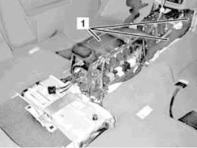
1 - Air ducts
Dashboard Installation Details (3 out of 12)
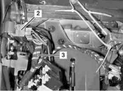
3 - Console wiring harness
Dashboard Installation Details (4 out of 12)
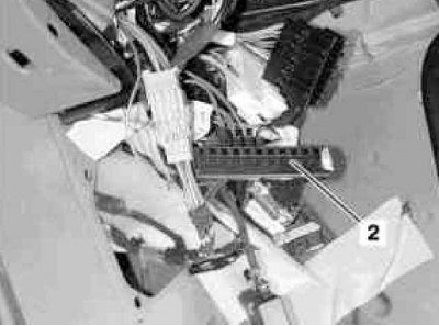
2 - Potential equalization block
Dashboard Installation Details (5 out of 12)
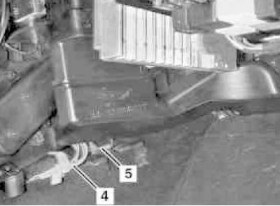
4 - Connecting wiring
5 - Ground/shield terminals
Dashboard Installation Details (6 out of 12)
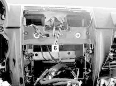
6 - Central fixing screws
Dashboard Installation Details (7 out of 12)
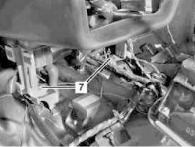
7 - Mounting screw
Dashboard Installation Details (8 out of 12)
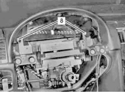
8 - Mounting bolt
Dashboard Installation Details (9 out of 12)
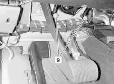
9 - Fixing nut
Dashboard Installation Details (10 out of 12)
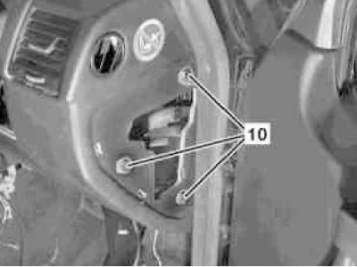
10 - Mounting screw
Dashboard Installation Details (11 out of 12)
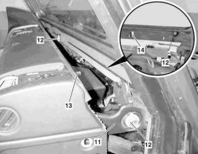
11 - Mounting bracket; 12 - Regulator; 13 - Pin; 14 - Groove

Dashboard Installation Details (12 out of 12)
12 - Regulator
1. On models of the corresponding configuration (code ET2) activate the service mode of the TELE AID emergency call system (see Section Activation / deactivation of the service mode of the TELE AID emergency call system).
2. Disconnect the negative cable from the battery.
3. Remove the lower left section of the instrument panel trim (see Section Removal and installation of the left lower section of finishing of the panel of devices).
4. Remove the electrically adjustable steering column (see chapter Suspension and steering).
5. Remove the left instrument panel cover.
6. Remove from the mounting block (F34) electronic ignition switch fuses (EIS/EZS) (31) and instrument clusters (42).
7. Remove AT control modules (ETC) and, - on models of the corresponding configuration (ET code, except 463.246/249), - TELE AID emergency call systems (see chapter Onboard electrical equipment).
8. Remove the padded under the center console (1) three air ducts for heating/ventilation systems.
9. Disconnect the console harness connectors (3) with the wiring of the driver's foot well, - try to remember the installation positions of the connectors, as well as the routes for laying the harnesses.
10. In the driver's foot well, remove the connectors from the potential equalization block (2).
11. Disconnect the CAN data bus ground and shield leads from the ground point at the base of the left A-pillar.
12. Remove the front ashtray (see Section Removal and installation of a forward ashtray).
13. Remove the facing panel of the console section of the instrument panel (see Section Removal and installation of the facing panel of the console section of the instrument panel).
14. Remove the loudspeaker mounted in the central part of the instrument panel (see chapter Onboard electrical equipment).
15. Remove the radio (see chapter Onboard electrical equipment).
16. Appropriate models (code ET4) remove the assembly of the multifunction display / control module of the COMAND system (see chapter Onboard electrical equipment).
17. Mark installation positions of electric sockets in selections in the central part of the panel of devices.
18. Remove the right instrument panel cover.
19. Remove glove box assembly (see Section Removal and installation of a ware box).
20. Remove the right lower instrument panel cover (see Section Removal and installation of the lower covers of the panel of devices).
21. Disconnect the wiring (4) from the potential equalization block / distributor of the CAN data bus under the casing of the A/C evaporator, - try to remember the routes for laying the harnesses.
22. Disconnect the ground and shield leads (5) from the ground point - again try to remember the routes for laying the harnesses.
23. Turn out the central bolts (6) attaching the instrument panel assembly to the bulkhead of the engine compartment.
24. Remove the bolts (7) attaching the instrument panel to the transmission line tunnel.
25. Remove the bolts (8) fastening the steering column jacket bracket on the top of the engine compartment bulkhead, - the bolts are placed under the instrument panel mounting bracket.
26. Give nuts (9) fixing the bracket of the steering column jacket on the bulkhead of the engine compartment in the driver's foot well, - if necessary, block the heads of the mating bolts on the engine side from rotating.
27. Remove the screws (10) (three on the right and three on the left) mounting bracket fasteners (11) instrument panels.
28. Filing up with a turn, remove the instrument panel, if necessary, use the help of an assistant.
29. Installation is carried out in the reverse order - with the appropriate configuration (code ET2) deactivate the service mode of the TELE AID system (see Section Activation / deactivation of the service mode of the TELE AID emergency call system).
30. Finally, read the DTCs and clear the OBD memory using the STAR DIAGNOSIS scanner (6511 1801 00) (see chapter Engine Electrical Systems).