
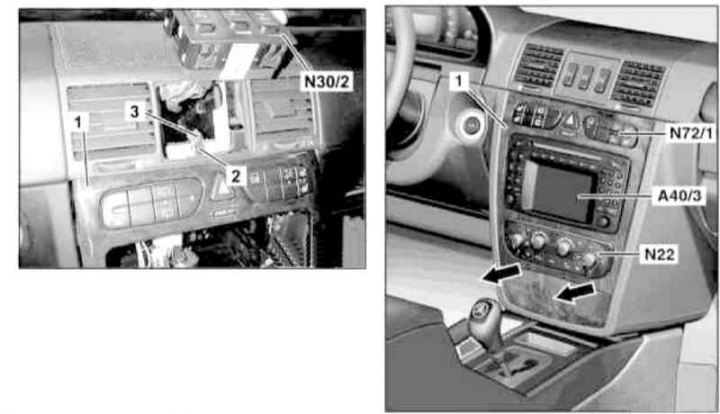
Details of installation of facing of the central/console section of the instrument panel
1 - Facing panel; 2 - Mounting plate; 3 - Bolt; A40 / 3 - Multifunctional display / control module of the COMAND system; N22 - Automatic A/C activation button; N30/2 - Assembly of differential lock switches; N72 / 1 - Left upper group of switches of the console section of the instrument panel
1. On models of the corresponding configuration (code ET2) activate the service mode of the TELE AID emergency call system (see Section Activation / deactivation of the service mode of the TELE AID emergency call system).
2. Move the AT selector lever to position «D».
3. Disconnect the negative cable from the battery.
4. Remove the differential lock switch assembly (N30/2) (see chapter Onboard electrical equipment) and, without disconnecting the wiring, set it aside.
5. Remove the bolt (3) and remove the mounting plate (2).
6. Open the front ashtray and remove the trim panel (1), for which first slide it down, then pull it out.
7. Disconnect the connector (N22) wiring of the K / V activation button and finally remove the panel (1).
8. Installation is carried out in the reverse order, - with the appropriate configuration (code ET2) deactivate the service mode of the TELE AID system (see Section Activation / deactivation of the service mode of the TELE AID emergency call system).
9. Finally, read the DTCs and clear the OBD memory using the STAR DIAGNOSIS scanner (6511 1801 00) (see chapter Engine Electrical Systems) and enter the required basic settings for the on-board equipment.