
Models Convertible/short base
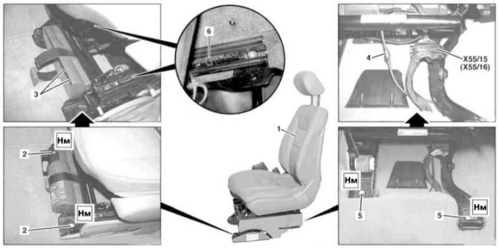
Front seat installation details on Convertible models (1 of 2)
1 - Assembling the front seat; 2 - Front seat frame mounting bolts; 3 - Bolts for fastening the mounting bracket of the fire extinguisher; 4 - Pneumatic line; 5 - Rear seat frame mounting bolts; 6 - Seat adjuster stop; X55 / 15 - Driver's seat wiring connector; X55 / 16 - Passenger seat wiring connector
Front seat installation details on Convertible models (2 of 2)
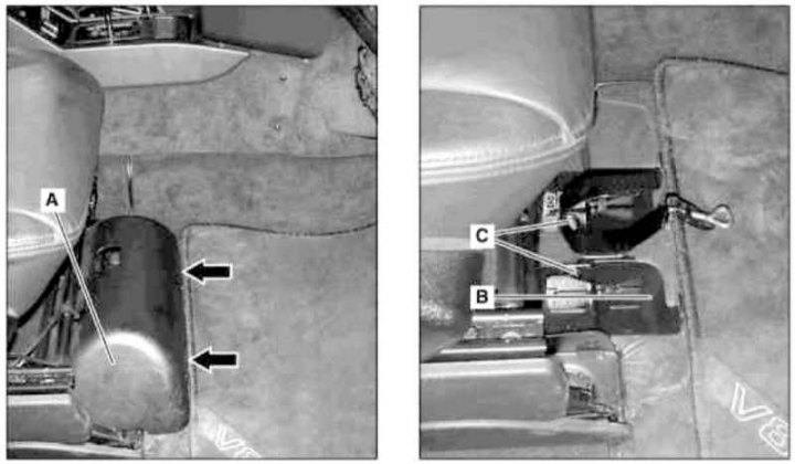
A - Access cover to the jack; B - Jack mounting bracket; C - Bolts; Arrows - Clips
1. Remove the stop (6) seat adjuster.
2. Slide the seat assembly (1) forward and remove the rear bolts (5) frame fasteners.
3. Slide the seat assembly (1) back.
4. Release the latches (arrows) and remove the cover (A) jacking department (passenger seat only).
5. Remove the jack, then remove the bolts (WITH) and remove the mounting bracket (IN) jack mounts (passenger seat only).
6. Remove the front bolts (2) seat frame fasteners.
7. Appropriate models (code ET2) activate the service mode of the TELE AID emergency call system (see Section Activation / deactivation of the service mode of the TELE AID emergency call system).
8. Disconnect the negative cable from the battery.
9. Remove the fire extinguisher (driver's seat only).
10. Remove the screws (3) fire extinguisher mounting bracket (driver's seat only).
11. Tilt the seat forward and disconnect the connector (X55/15 or X55/16) wiring.
12. Appropriate models (code SM7 and SM/8) disconnect the pneumatic line (4) multi-loop adjustment.
13. Remove the front seat assembly (1).
14. Installation is carried out in the reverse order - when installing the stop (6) leave at least two teeth of the adjusting rack free.
15. Appropriate models (code ET2) deactivate the service mode of the TELE AID system (see Section Activation / deactivation of the service mode of the TELE AID emergency call system).
16. Finally, read the DTCs and clear the OBD memory using the STAR DIAGNOSIS scanner (6511 1801 00) (see chapter Engine Electrical Systems), and check that the power seat is working properly.
Models Wagon
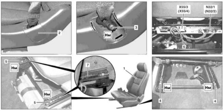
Front seat installation details on Wagon models
1 - Assembly of the seat; 2 - Plug; 3 - Bolt of the anchor assembly of the seat belt; 4 - Rear seat frame mounting bolts; 5 - Front seat frame mounting bolts; 6 - Pneumatic connector; 7 - Regulator stop; N32 / 1 - Driver's seat / steering column adjustment control module with settings memory; N32/2 - Passenger seat adjustment control module with settings memory; X55 / 3 - Connector for heating the driver's seat; X55 / 4 - Passenger seat heating wiring connector
1. Slide the seat assembly (1) to the rearmost position and remove the stop (7) regulator.
2. Slide the seat assembly forward.
3. Remove the decorative cap (2) and unscrew the anchor bolt (3) seat belt.
4. Turn out back bolts (4) frame fasteners, then slide the seat (1) back and remove the front bolts (5).
5. Appropriate models (code ET2) activate the service mode of the TELE AID emergency call system (see Section Activation / deactivation of the service mode of the TELE AID emergency call system).
6. Disconnect the negative cable from the battery.
7. Disconnect drive wiring connectors (N32/1 or N32/2) And (on models of the corresponding configuration, - code H10) heating (X55/3 or X55/4) seats.
8. Appropriate models (code SM7 and SM/8) disconnect the pneumatic connector (6) multi-loop adjustment.
9. Remove the front seat assembly (1).
10. Installation is carried out in the reverse order - when installing the stop (6) leave at least two teeth of the adjusting rack free.
11. Appropriate models (code ET2) deactivate the service mode of the TELE AID system (see Section Activation / deactivation of the service mode of the TELE AID emergency call system).
12. Finally, read the DTCs and clear the OBD memory using the STAR DIAGNOSIS scanner (6511 1801 00) (see chapter Engine Electrical Systems), and check that the power seat is working properly.