
Headlining installation details on Wagon models (1 of 5)
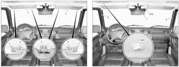
1, 2 - Sun visors; 3 - Bolt; 4 - Supports; 5 - Holder; 6 - Cover; 7 - Cabin rear-view mirror; 8, 9 - A-pillar finishing panels; B25 - Hands-free device system microphone; N70 - Overhead console switch panel
Headlining installation details on Wagon models (2 out of 5)
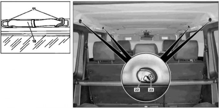
10 - Handle; 11 - Covers; 22 - Luggage net attachment points; 23 - Bolt
Headlining installation details on Wagon models (3 out of 5)
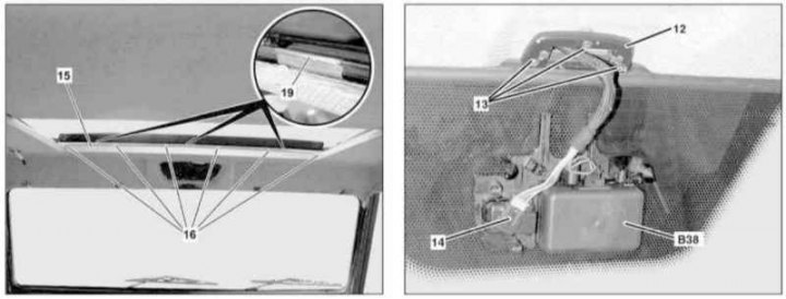
12 - Support for the interior rear-view mirror; 13, 16 - Screws; 14 - Wiring connector; 15 - Chrome lining; 19 - Metal retainer; B38 - Rain sensor
Headlining installation details on Wagon models (4 out of 5)
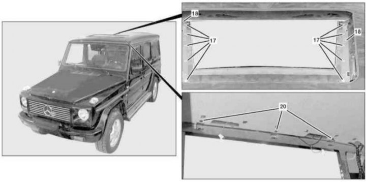
17 - Screws; 18 - Guides; 20 - Fixing screws
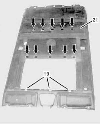
Headlining installation details on Wagon models (5 out of 5)
19 - Metal retainer; 21 - Headlining
1. Fully open the top hatch.
2. Appropriate models (code ET2) activate the service mode of the TELE AID emergency call system (see Section Activation / deactivation of the service mode of the TELE AID emergency call system).
3. Remove the left front seat assembly with frame (see Section Removal and installation of front seat assemblies).
4. Turn on the auxiliary battery and connect it to the standard battery, then disconnect the negative cable from the latter.
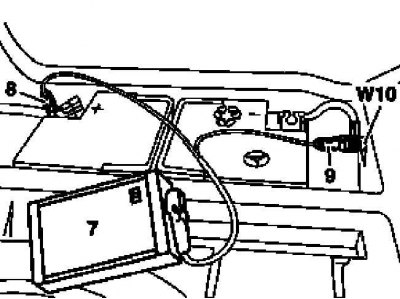
7 - Auxiliary battery
8 - Module positive wire terminal
9 - Terminal of the negative wire of the module
W10 - Battery Ground
5. Expand to the sides, unscrew from the support brackets (4) screws (3), if equipped, disconnect the wiring connector and remove the sun visors (1 and 2).
6. Unscrew located under the decorative covers (6) fixing screws and remove the holders (5) sun visors (1 and 2).
7. Remove switch panel (N70) ceiling console (see chapter Onboard electrical equipment).
8. Remove the interior rearview mirror (7) (see Section Removal and installation of a saloon rear-view mirror).
9. On models of the appropriate configuration, carefully pry and release from the ceiling upholstery (21) microphone (B25) Hands-free/Linguatronic devices, disconnect the wiring from the microphone.
10. Remove the assembly of the left rear seat with backrest (see Section Removal and installation of front seat assemblies).
11. Remove panels (8 and 9) A-pillar finishes (see Section Removal and installation of trim panels body pillars).
12. Remove the finishing panels of the B-pillars (see Section Removal and installation of trim panels body pillars).
13. Remove the side trim panels (see Section Removal and installation of trim panels).
14. Remove the rear cabin lights (see chapter Onboard electrical equipment).
15. Remove the rear top trim panel (see Section Removal and installation of trim panels).
16. Turn out located under covers (11) mounting bolts and remove the upper handles (10).
17. If equipped, remove the fixing screws (23) and remove the luggage net attachment points (22).
18. Remove directional rear lights (see chapter Onboard electrical equipment).
19. Turn out bolts (13), disconnect the connector (14) rain sensor (B38) and remove the support bracket (12) saloon rear-view mirror.
20. Remove the upholstery of the top hatch cover (see Section Removal and installation of the panel of an upholstery of a cover of the top hatch).
21. Remove six screws (16) and remove the chrome trim (15) top hatch frame.
22. Remove the bolts (17) both guides (18) top hatch.
23. Peel off the upholstery carefully (21) from the ceiling panel at the gluing points in the area of the upper hatch opening.
24. Release the metal clips (19) and release the upholstery (21) from the hatchway.
25. Remove the bolts (20) ceiling lining fixings (21).
26. Peel off the upholstery (21) from Velcro fasteners (arrows) and, moving it diagonally back, remove it from the car.
27. Installation is carried out in the reverse order - make sure that the wiring is correct (3) sensor to sample (4).
28. Finally, read the DTCs and clear the OBD memory using the STAR DIAGNOSIS scanner (6511 1801 00) (see chapter Engine Electrical Systems).