



Contents: Front seats ↡ Rear seats ↡
Front seats
Convertible/short wheelbase models
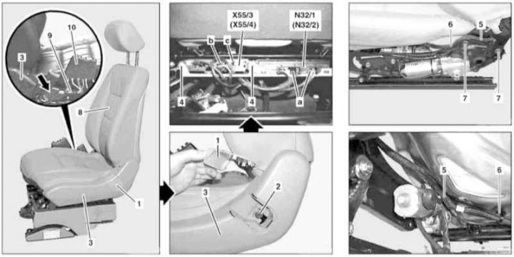
Front Seat Back Installation Details (convertible/short wheelbase models)
1 - Plug; 2 - Screw; 3 - Finishing panel; 4 - Connection block screws; 5 - Electrical wiring; 6 - Harness; 7 - Backrest mounting bolts; 8 - Back; 9 - Pneumatic line; 10 - Control valve; a, b, c - Control module wiring connectors; N32/1 - Driver's seat/steering column adjustment control module with setting memory; N32/2 - Passenger seat adjustment control module with setting memory; X55/3 - Driver's seat heating wiring connector; X55/4 - Passenger seat heating wiring connector; Arrow - Sealing plug
1. Remove the front seat assembly (see Section Removal and installation front seat assemblies).
2. Remove the plug (1) and unscrew the screw (2) from the trim panel (3).
3. Remove the sealing plug (arrow) and unscrew the mounting screw located underneath it.
4. Press back, release from the clips and remove the side trim panel (3).
5. Disconnect the control module wiring connector (a) (N32/1 or N 32/2).
6. After marking the installation positions, disconnect the connectors (b and c) on the block (X55/3 or X55/4).
7. Remove the screws (4) of the connection block.
Publication reprinted from this resource MercedesMan.ru
8. On models with the corresponding configuration (code SM7 and SM/8) remove the check valve (10) and disconnect the pneumatic line (9) of the multi-circuit adjustment.
9. Move aside the electrical wiring (5) and (with appropriate equipment) pneumatic line, - the strapping bandages (6) must be replaced without fail.
10. Unscrew the fastening bolts on the left and right sides and remove the seat back (8).
11. Installation is carried out in the reverse order - make sure that the electrical wiring is connected correctly.
Models Universal
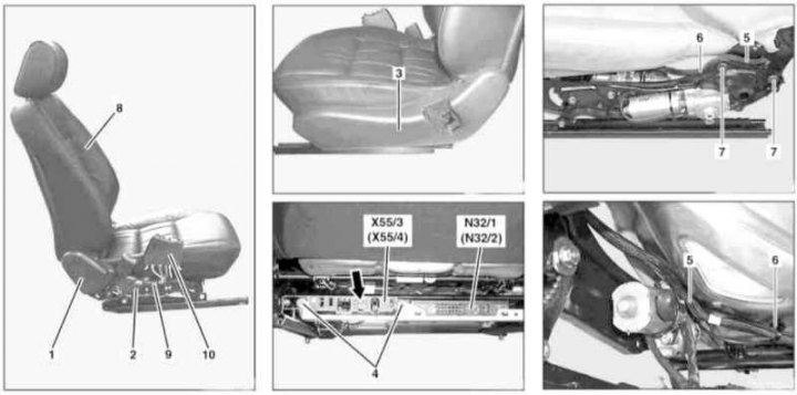
Front Seat Back Installation Details (models Universal)
1 - Right trim panel; 2 - Mounting bolt; 3 - Left trim panel; 4 - Connection block screws; 5 - Electrical wiring; 6 - Harness; 7 - Backrest mounting bolts; 8 - Back; 9 - Pneumatic line; 10 - Control valve; a, b, c - Control module wiring connectors; N32/1 - Driver's seat/steering column adjustment control module with setting memory; N32/2 - Passenger seat adjustment control module with setting memory; X55/3 - Driver's seat heating wiring connector; X55/4 - Passenger seat heating wiring connector; Arrow - Electrical wiring connector
1. Remove the front seat assembly (see Section Removal and installation front seat assemblies).
2. Remove the sealing plug, unscrew the fastening screw (2) and remove the right trim panel (1).
3. The left trim panel (3) is removed in the same way as on the Convertible models (see paragraphs 2 through 4).
4. Disconnect the control module wiring connector (5) (N32/1 or N 32/2).
5. On models with heated seats (code H10), disconnect the connectors (X55/3 or X55/4) corresponding electrical wiring. Also release the connector indicated by the arrow and release both backrest heating wires (8) from its casing, having previously marked them.
6. On models with the corresponding configuration (code SM7 and SM/8) remove the check valve (10) and disconnect the pneumatic line (9) of the multi-circuit control.
7. Then proceed in a manner similar to that described above for the Convertible models (see paragraphs 9 to 11 above).
Rear seats
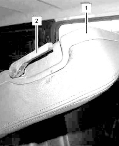
Rear Seat Back Installation Details (1 of 2)
1 - Finishing panel; 2 - Backrest lock release lever
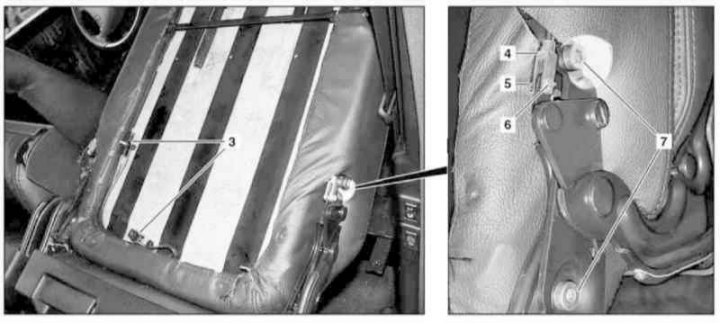
Rear Seat Back Installation Details (2 of 2)
3 - Heating wiring connectors (R13/6x1, - left, or R13/8x1, - right); 4 - Backrest locking mechanism; 5 - Locking washer for blocker bolts; 6 - Backrest lock bolts; 7 - Backrest mounting screws
1. Remove the rear head restraints and fold the seatback forward.
2. Pry off the backrest lock release lever (2).
3. Remove the mounting screws and remove the trim panel (1).
4. On models with the corresponding configuration (code H11), disconnect the connectors (3) of the backrest heating wiring (R13/6x1 or R13/8x1), cut the binding bandages and release the wires from the back.
5. Remove the lock washer (5), unscrew the bolts (6) and detach the backrest locking mechanism.
6. Unscrew the fastening bolts (7) and remove the backrest.
7. Installation is carried out in reverse order.