
Models 463.250/323/333
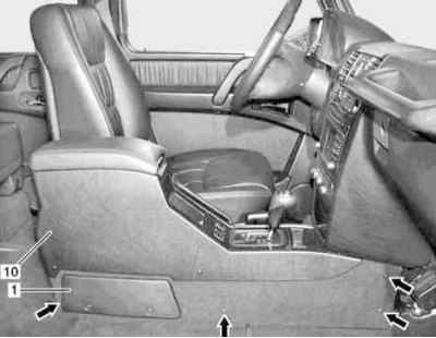
Installation details of the center console on models 463.250/323/333 (1 of 5)
1 - Cover of the mounting block of fuses; 10 - Center console
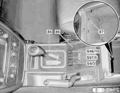
Installation details of the center console on models 463.250/323/333 (2 out of 5)
85 - Facing frame; 86 - Wooden panel; 87 - Bolts; S4 / 3 - Switch for additional heating system (only diesel models); S46/10 - Interior heating/ventilation switch, independent action (with appropriate equipment); S97/5 - Transfer case switch
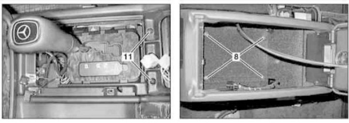
Installation details of the center console on models 463.250/323/333 (3 out of 5)
8, 11 - Bolts
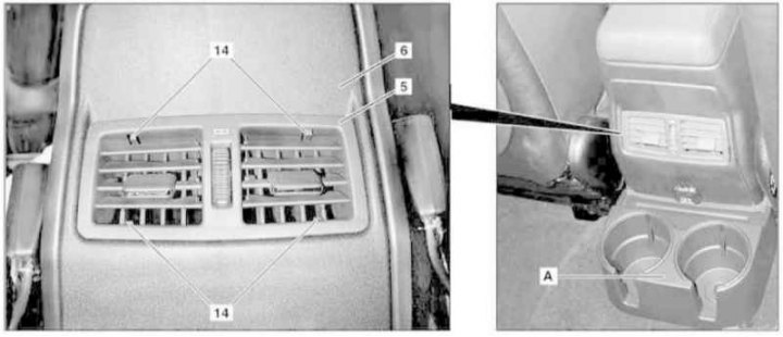
Center console installation details (all models) (4 out of 5)
5 - Console deflectors; 6 - Cover; 14 - Clips; A - cup holder
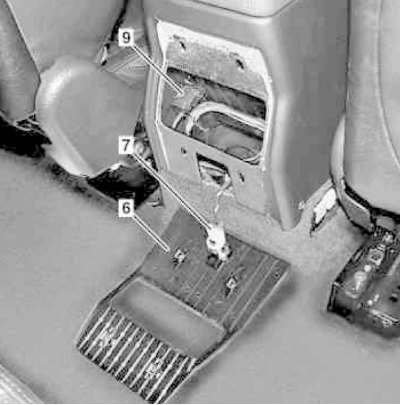
Center console installation details (all models) (5 out of 5)
6 - Cover; 7 - Power outlet; 9 - Telephone socket
1. Unscrew the bolt located at the bottom and remove the cover of the fuse mounting block (1).
2. Remove side bolts (arrows) center console mountings (10), - Move the front seats to a comfortable position to gain access to the bolts.
3. Appropriate models (code ET2) activate the service mode of the TELE AID emergency call system (see Section Activation / deactivation of the service mode of the TELE AID emergency call system).
4. Remove the key from the ignition lock.
5. Turn on the auxiliary battery and connect it to the standard battery, then disconnect the negative cable from the latter.
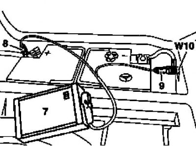
7 - Auxiliary battery
8 - Module positive wire terminal
9 - Terminal of the negative wire of the module
W10 - Battery Ground
6. Remove trim frame (85) covers of the basis of the lever of the selector АТ.
7. Turn out fixing bolts (87), located inside the console glove box.
8. Gently release from the console assembly (10) front wooden panel (86).
9. Disconnect wiring from console switches (S4/3, S46/10 and S97/5).
10. Turn out fixing bolts (8).
11. Remove the parking brake lever cover.
12. Gently release the latches (14) and remove assembly (5) rear cantilever vents for interior heating/ventilation systems.
13. Remove the cup holder (A).
14. Release the four latches (two up and two down) and remove the cover (6).
15. Disconnect the electrical wiring from the power outlet (7).
16. Disconnect phone jack (9).
17. Turn out bolts (11).
18. Apply the parking brake.
19. Remove the center console assembly (10), by pushing it back and up.
20. Installation is carried out in the reverse order, - with the appropriate configuration (code ET2) deactivate the service mode of the TELE AID system (see Section Activation / deactivation of the service mode of the TELE AID emergency call system).
21. Finally, read the DTCs and clear the OBD memory using the STAR DIAGNOSIS scanner (6511 1801 00) (see chapter Engine Electrical Systems).
Models 463.246/249
The corresponding illustrative material is presented in Ref. illustrations and illustrations Installation details of the center console on models 463.250/323/333 (2 out of 5) and Installation details of the center console on models 463.250/323/333 (3 out of 5), which includes all references in the text.
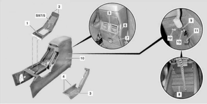
Installation details of the center console on models 463.246/249 (see also illustrations Center console installation details (all models) (4 out of 5) and Details of the installation of the center console (all models) (5 out of 5))
1 - Overlay; 2 - Clamps; 3 - Parking brake lever cover; 5 - Console deflectors; 6, 8 - Covers; 7 - Power socket; 9 - Connector; 10 - Console assembly; 11 - Telephone socket; 12 - Antenna cable; 13 - Retainer; S97/5 - Transfer case switch
1. Remove the key from the ignition switch.
2. Turn on the auxiliary battery and connect it to the standard battery, then disconnect the negative cable from the latter.

7 - Auxiliary battery
8 - Module positive wire terminal
9 - Terminal of the negative wire of the module
W10 - Battery Ground
3. Remove the cover (3) parking brake lever.
4. Remove the cup holder (A).
5. Gently release the latches (14) and remove assembly (5) rear cantilever vents for interior heating/ventilation systems.
6. Release the four latches (two up and two down) and remove the cover (6).
7. Disconnect the electrical wiring from the power outlet (7).
8. Inside the console storage box, remove the cover (8) and unplug the connector (9).
9. Release the connectors from the console assembly (9 and 11), and an antenna cable (12), after releasing the latch (13).
10. Turn out fourteen fixing screws and remove assembly of the central console (10).
11. Installation is carried out in the reverse order.
12. Finally, read the DTCs and clear the OBD memory using the STAR DIAGNOSIS scanner (6511 1801 00) (see chapter Engine Electrical Systems).