
Central deflectors
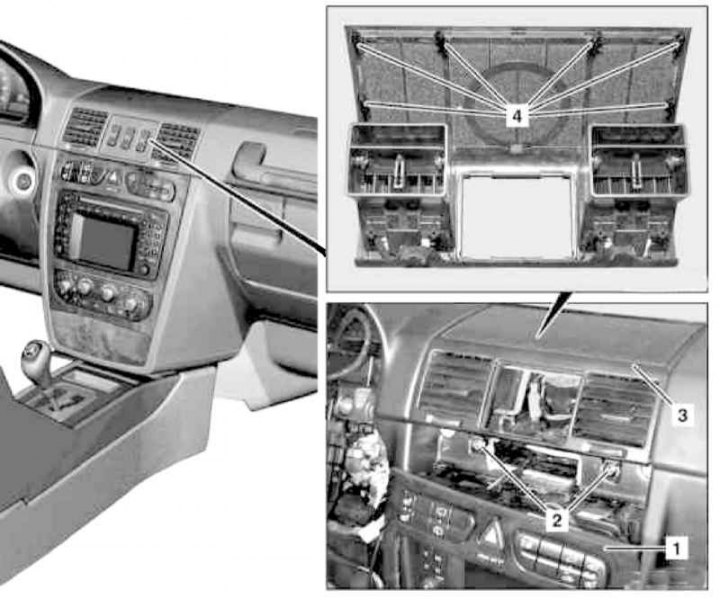
Details of installation of deflectors of the central air duct of the instrument panel
1 - Panel of groups of switches of the central section of the instrument panel; 2 - Bolts; 3 - Assembly of deflectors; 4 - Clips
1. On models of the corresponding configuration (code ET2) activate the service mode of the TELE AID emergency call system (see Section Activation / deactivation of the service mode of the TELE AID emergency call system).
2. Disconnect the negative cable from the battery.
3. Remove the differential lock drive switch group (see chapter Onboard electrical equipment).
4. Remove the panel (1) groups of switches of the console section of the instrument panel (see chapter Onboard electrical equipment). There is no need to disconnect the electrical wiring - it will be enough just to provide access to the mounting screws (2).
5. Remove the screws (2) and remove assembly (3) central deflectors, pulling it up with a turn from the instrument panel - try not to damage the latches (4).
6. Installation is carried out in the reverse order - make sure that the deflector nozzles are properly seated on their air ducts.
7. Appropriate models (code ET2) deactivate the service mode of the TELE AID system (see Section Activation / deactivation of the service mode of the TELE AID emergency call system).
8. Finally, read the DTCs and clear the OBD memory using the STAR DIAGNOSIS scanner (6511 1801 00) (see chapter Engine Electrical Systems).
Side deflectors
Left side of instrument panel
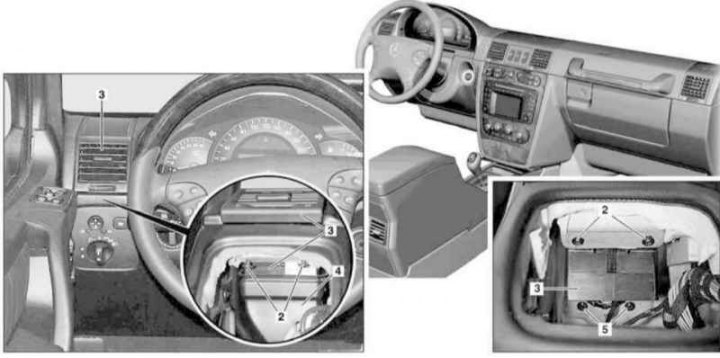
Installation details of the side deflectors on the left side of the instrument panel
2, 5 - Mounting screws; 3 - Deflector; 4 - Air duct sleeve
1. Remove the lighting mode switch (see chapter Onboard electrical equipment).
2. Disconnect the air duct from the deflector assembly nozzle (4).
3. Depending on the version, carefully loosen the two latches with a long wedge of a suitable shape / remove the fixing screws (2) / (2 and 5) and remove the deflector (3), pulling its top with a turn and releasing it from the instrument panel, - prepare a replaceable side support assembly.
4. Installation is carried out in the reverse order.
Right side of instrument panel
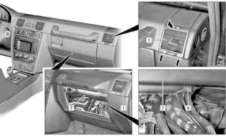
Installation details of the side deflectors on the right side of the instrument panel
1 - Deflector; 6 - Fixing screw; 7 - Air duct sleeve
1. Remove the lower cover on the right under the instrument panel (see Section Removal and installation of the lower covers of the panel of devices).
2. Remove the glove box (see Section Removal and installation of a ware box).
3. Turn out the screw of fastening of the right air duct (7) interior ventilation/heating systems.
4. Separate the duct (7) from the deflector assembly nozzle (1), - loudspeaker wiring is fixed on the air duct sleeve.
5. Next, proceed in the same manner as described above for the left deflector (see above paragraph 3 of subsection Left side of the instrument panel).
6. Installation is carried out in the reverse order.