



Contents: Right cover ↡ Left cover ↡
Right cover
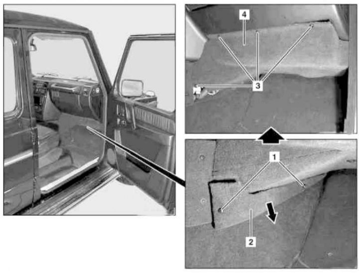
Installation details of the right lower cover of the instrument panel
1, 3 - Bolts; 2 - Overlay; 4 - Lid
1. Loosen the mounting bolts (1) and remove the cover (2) by pulling it down in the direction indicated by the arrow.
2. Unscrew the bolts (3) and remove the cover (4).
3. On models with the corresponding equipment (code E2), disconnect the electrical wiring from the right front loudspeaker of the TELE AID emergency call system.
4. Installation is carried out in the reverse order - ensure that the cover (4) is correctly positioned relative to the air duct of the ventilation/heating systems of the passenger compartment.
Left cover
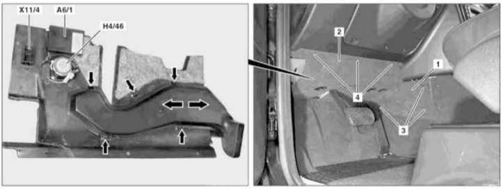
Installation details of the left lower cover of the instrument panel
1 - Tunnel section trim panel; 2 - Lid; 3, 4 - Bolts; A6/1 - Additional heater receiver (STH); H4/46 - Left front speaker of the TELE AID system; X11/4 - Diagnostic connector DLC
1. On models with the corresponding configuration (code ET2), activate the service mode of the TELE AID emergency call system (see Section Activation/deactivation of the service mode of the TELE AID emergency call system).
2. Disconnect the negative cable from the battery.
3. Loosen the mounting bolts (3) and remove the right side panel (1) of the driver's footwell trim.
4. Remove the bolts (4) and lower the left lower cover (2) of the instrument panel.
5. Unlock and disconnect the diagnostic connector DLC (X11/4), if equipped, disconnect the electrical wiring from the STH additional heater receiver (A6/1) (code H12) and the right front loudspeaker of the TELE AID emergency call system (H4/46) (code E2).
6. Lower it even further and turn it to remove the cover (2).
7. Installation is carried out in the reverse order - ensure that it fits correctly in the guides and that it snaps securely into the latches of the air duct of the interior ventilation/heating systems.
8. On models with the corresponding configuration (code ET2), deactivate the service mode of the TELE AID system (see Section Activation/deactivation of the service mode of the TELE AID emergency call system).
9. Finally, read the DTC codes and clear the on-board diagnostic system memory using the STAR DIAGNOSIS scanner (6511 1801 00) (See Chapter Engine electrical systems).