
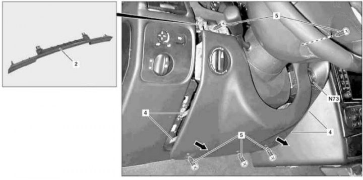
Installation details of the left lower section of the instrument panel trim
2 - Facing plate; 4 - Guide pin; 5 - Mounting screws; N73 - EIS/EZS module
1. On models of the corresponding configuration (code ET2) activate the service mode of the TELE AID emergency call system (see Section Activation / deactivation of the service mode of the TELE AID emergency call system).
2. Move the adjustable steering column to its highest position.
3. Turn on the auxiliary battery and connect it to the standard battery, then disconnect the negative cable from the latter.
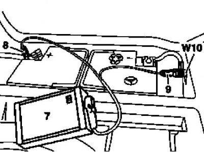
7 - Auxiliary battery
8 - Module positive wire terminal
9 - Terminal of the negative wire of the module
W10 - Battery Ground
4. Using a suitable wedge, release the four latches and remove the trim strip (2).
5. Rotate to position «0», then remove the headlight leveling knob (except models 463.246/249).
6. Remove the fixing screws (5).
7. Pull up with a twist to remove from the guide pins (4) the lower section of the instrument panel trim.
8. Remove and, without disconnecting the wiring, set aside the headlamp leveling switch module (except models 463.246/249).
9. Using a special nozzle (210 589 00 07 00) remove the EIS/EZS module (N73).
10. Having given in the direction specified by an arrow, remove the bottom section of furnish of the panel of devices.
11. Installation is carried out in the reverse order, - with the appropriate configuration (code ET2) deactivate the service mode of the TELE AID system (see Section Activation / deactivation of the service mode of the TELE AID emergency call system).
12. Finally, read the DTCs and clear the OBD memory using the STAR DIAGNOSIS scanner (6511 1801 00) (see chapter Engine Electrical Systems).