
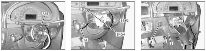
Steering Column End Cover Installation Details on 30.06.02 Release Models (1 of 2)
2 - The lower section of the instrument panel trim; 3 - Headlight adjustment switch; A45 - Contact cable drum; S4 - Assembling the steering column switches; S40/4 - Tempostat switch; S93/2 - Right steering column switch
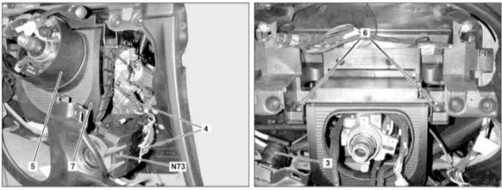
Steering column end cap installation details (2 of 2)
4 - Wiring connectors; 5 - Cylindrical casing; 6 - Mounting bolts; 7 - End cap; N73 - EIS/EZS module
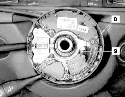
Installation details of the end cover of the steering column of the release from 01.07.02
8 - Assembling the steering column switches
9 - Clamping screw
1. Turn the steering wheel to the straight ahead position.
2. Appropriate models (code ET2) activate the service mode of the TELE AID emergency call system (see Section Activation / deactivation of the service mode of the TELE AID emergency call system).
3. Turn on the auxiliary battery and connect it to the standard battery, then disconnect the negative cable from the latter.
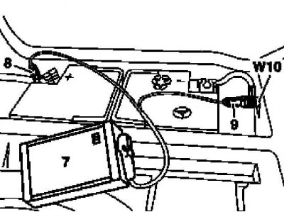
7 - Auxiliary battery
8 - Module positive wire terminal
9 - Terminal of the negative wire of the module
W10 - Battery Ground
4. Remove the steering wheel (see chapter Suspension and steering).
5. Remove left lower section (2) instrument panel trim (see Section Removal and installation of the left lower section of finishing of the panel of devices).
6. Remove the contact cable drum (A45) horn and driver's airbag (see chapter Suspension and steering).
7. Remove the combined steering column switch assembly (S4 or 8).
8. On models manufactured before 06/30/02, disconnect the connectors (4) EIS/EZS module (N73) and instrument panel wiring harness.
9. Remove the instrument cluster (see Section Removal and installation of a combination of devices).
10. On models manufactured before 06/30/02, remove the cylindrical casing (5) steering column - try to remember the routes of wiring.
11. Turn out bolts (6) and remove the end cap (7) steering column.
12. Installation is carried out in the reverse order, - with the appropriate configuration (code ET2) deactivate the service mode of the TELE AID system (see Section Activation / deactivation of the service mode of the TELE AID emergency call system).
13. Finally, read the DTCs and clear the OBD memory using the STAR DIAGNOSIS scanner (6511 1801 00) (see chapter Engine Electrical Systems) and enter the required basic settings for the on-board equipment.