
For models 463.246/249 of the corresponding configuration
Details of installation of a knee support on models 463.246/249 of the corresponding complete set
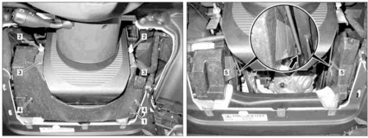
1 - Knee support; 2 - Fixing nuts; 3 - Pressure plates; 4 - Mounting bolts; 5 - Mounting bracket
1. Remove the lower trim section from the driver's side of the instrument panel (see Section Removal and installation of the left lower section of finishing of the panel of devices), - the need to dismantle the electronic ignition switch module (EIS/EZS) absent.
2. Loosen the fixing nuts (2) and remove the pressure plates (3).
3. Turn out bolts (4) and remove knee brace (1).
4. Installation is carried out in the reverse order - make sure that the mounting bracket (5) did not pop out of the mounting hole (arrow), and when screwing the fixing bolts (4) stop material was not deformed (1).