



Contents: Removal ↡ Installation ↡
Removal
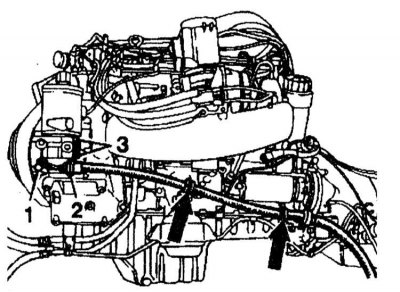
Removal the pump assembly
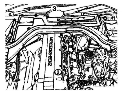
1 - Pump
2 - Support bracket
3 — M8 bolts for fastening the pump assembly
1. Disconnect the negative cable from the battery.
2. On models with air conditioning: Attach the protective plate to the air conditioning condenser. Disconnect the oil lines from the oil cooler.
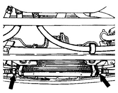
3. Loosen the clamps securing the oil lines to the body.
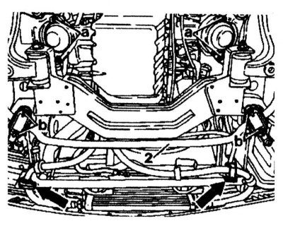
4. Remove the air conditioning compressor drive belt.
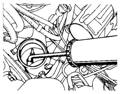
5. Use a pump to pump out the fluid from the power steering reservoir.
6. Disconnect the air conditioning compressor from the engine. To do this, unscrew the bolts (35) and nuts securing the pipelines. Secure the compressor to the side at the bottom of the engine compartment with the pipelines attached.
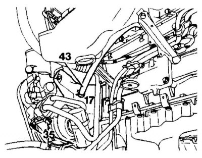
7. Disconnect the return and pressure lines from the power steering pump and dual high pressure pump.
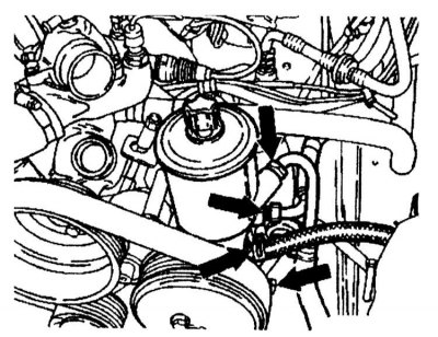
8. Unscrew the discharge pipe from the pump (1), unscrew the M8 bolts (3) securing the pump to the bracket (2) and disconnect the discharge pipe from the clamps.
9. Open the fuel filler cap to relieve pressure in the fuel system. Unscrew the fuel lines.
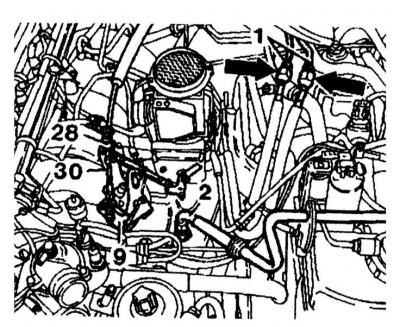
10. Disconnect the drive cable (30) from the control lever (5). To do this, squeeze the plastic clamp (28).
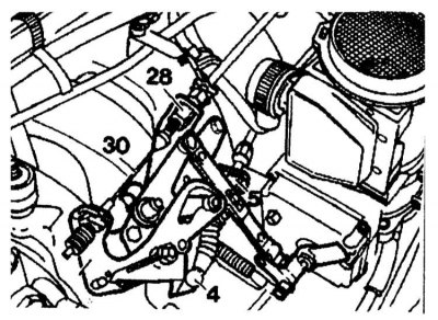
11. Disconnect the heater hoses and vacuum pipes in the engine compartment. On models with automatic transmission: disconnect the vacuum pipe from the 2-way valve.
12. Remove the cover (3), open the cable duct (1) and disconnect it on the right side.
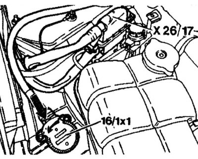
13. Disconnect the connectors (X26/17) and (X16/1x1) of the engine wiring. Press the pawl and turn it 90° to the left to disconnect the connector (X16/1x1).
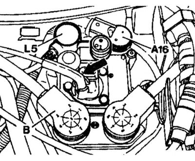
14. Disconnect the connector from the crankshaft position sensor (L5), from the control unit (B), knock sensors (A16) and disconnect the vacuum tubes.
15. Disconnect the fuel vapor recovery system suction pipe from the adapter in the left wheel arch.
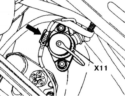
16. Disconnect the diagnostic connector (X11), disconnect the wiring connector from the TDC sensor from the rear diagnostic connector.
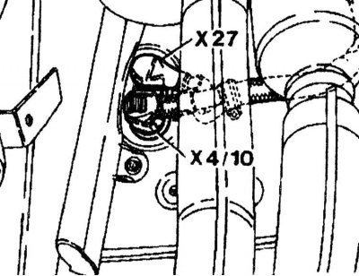
17. Unscrew the wire (X27) from the starter and the wire of chain 30 (X4/10) at the front right in the lower part of the engine compartment partition.
18. Disconnect the propeller shaft by unscrewing the mounting bolts.
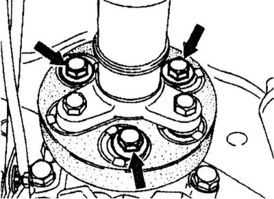
19. Loosen the bolts securing the propeller shaft intermediate bearing support, but do not remove it.
20. Loosen the cardan shaft nut. Move the cardan shaft back as far as possible.
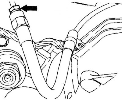
21. On models with automatic transmission, press out the locking levers and disconnect the gearshift rods from the gearshift lever. Disconnect the hydraulic line (arrow) of the clutch slave cylinder from the adapter.
22. On models with AT, loosen the mounting clamps (23) and unscrew the cable (6) from the downshift valve (61) or remove it.
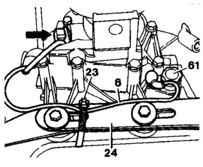
23. Unscrew the ground wire from the transmission.
24. Remove the connector from the starter interlock switch (8). The starter interlock switch connector is secured with a white plastic ring (arrow). Before removing the connector, the locking ring must be lifted and turned upward in the direction of the arrow. Disconnect the rod (9) from the gear selector lever.
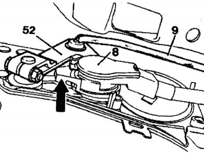
25. Using two screwdrivers, press the adapter (8) out of the cable.
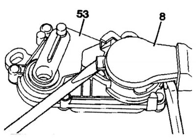
26. Disconnect the wiring connector from the transmission overload protection valve.
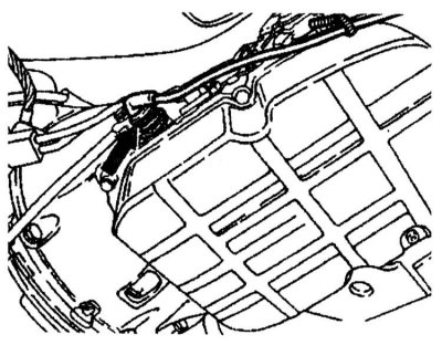
27. Attach the hoist to the engine lugs. Adjust the engine lift so that the engine can be jacked up horizontally. Raise the engine with the jack.
28. Unscrew the rear engine mounting bracket without supports. Unscrew the bolts (1).
29. Unscrew the bolts (2) of the transmission bracket (3).
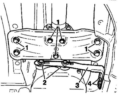
30. Unscrew the bolts a securing the left and right engine mounts.
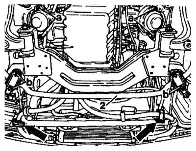
31. Lift the engine and gearbox and remove them from the engine compartment.
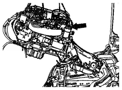
32. If necessary, remove the rear support.
Installation
Installation is performed in the reverse order of removal. Adjust the AT cables, oil level in the engine and gearbox.