
Common parameters
Note. Separate characteristics are also given in the text of the Chapter and, if they are mandatory, are highlighted in bold.
Engine
Note. The technical data has been determined according to EU directives. All data apply to vehicles with catalytic converter as standard. Depending on the items of special equipment, the data may differ from each other. You can get information on this issue at any Mercedes-Benz service station.
General characteristics
| Model | Release years | Code by VIN | Type of engine/fuel system | Volume, cm3 | Quantity and distribution c-ditch | Power, hp/kW | Torque, Nm | Max. speed, km/h | Notes |
| 300SE 2.8 | 92-93 | 140.028 | M104.944HFM | 2799 | R6 | 193/142 | 270 | 215 | |
| S280 | 93-94 | ||||||||
| 300SE (SEL) | 91-93 | 140.032 (033) | M104.990LH | 3199 | R6 | 231/170 | 315 | 225 | |
| S320 | 93-98 | M104.944HFM | |||||||
| 300SD | 91-93 | 140.134 | OM603.971 | 3449 | R6 | 150/110 | 330 | 185 | |
| S350 TD | 93-96 | ||||||||
| S300 TD | 96-98 | 140.135 | OM606.961 | 2996 | R6 | 177/130 | 330 | 205 | |
| 400SE (SEL) | 91-93 | 140.042 (043) | M119.971LH and M119.981ME | 4196 | V8 | 279/205 | 400 | 245 | |
| S420 | 93-98 | ||||||||
| 500SE (SEL) | 91-93 | 140.050 (051) | M119.970LH and M119.980ME | 4973 | V8 | 320/235 | 470 | 250 | Ogre. 270 km/h |
S500 | 93-98 | ||||||||
| 600SE (SEL) | 91-93 | 140.056 (057) | M120.980LH and M120.982ME | 5987 | V12 | 394/290 | 570 | 250 | Ogre. 290 km/h |
| S600 | 93-98 |
| Rated power, kW (hp) /at rpm) //Rated torque, Nm (at rpm) | |
| S280 | 142 (193) /5500//270/3750 |
| S320 | 170 (231) /5600//315/3750 |
| S420 | 205 (279) /5700//400/3900 |
| S300 | TDI 130 /4400//330/1600-3600 |
| S500 | 235 (320) /5600//470/3900 |
| S600 | 290 (394) /5200//570/3800 |
| Number of cylinders / Type / Displacement, cm3 / Designation | |
| S280 | 6/DOHC/2799/104 |
| S320 | 6/DOHC/3199/104 |
| S420 | 8/OHC/4196/119 |
| S300 | TDI 6/DOHC/2996/606 |
| S500 | 8/OHC/4973/119 |
| S600 | 12/OHC/5987/120 |
| Maximum revolutions, rpm | |
| S280 | 6400 |
| S320 | 6400 |
| S420 | 6000 |
| S300 | TDI 5300 |
| S500 | 6000 |
| S600 | 6000 |
| Compression ratio | |
| S280 | Data not provided |
| S320 | 10.0:1 |
| S420, S500 | 11.0:1 |
| S600 | Data not provided |
| S320CDI | Data not provided |
| Compression pressure, bar | |
| S280 S320 | 10-14 |
| S420, S500, S600 | 13.5-15.5 |
| S300 | TDI 26-32 |
| The order of operation of the cylinders | |
| S280, S320, S300 | TDI 1-5-3-6-2-4 |
| S420, S500 | 1-5-4-8-6-3-7-2 |
| S600 | 1-12-5-8-3-10-6-7-2-11-4-9 |
Drive belt
| (Alternator / power steering, air conditioning), mm | |
| S280 | 2170/2257 |
| S320 | 2337/2440 |
| S420, S500 | 2460/- |
| S300 | TDI 6PKx2080/6PKx2120 |
| S600 | 2585/- |
| valve clearances | are not regulated, because applied hydraulic compensators |
Engine overhaul
M104 series engines
Camshaft bearing dimensions
| Nominal diameter, mm | |
| Camshaft | 29.947 29.963 |
| cylinder head | 30.000 30.021 |
| Repair diameter, mm | |
| Camshaft | 30.434 30.450 |
| cylinder head | 30.500 30.525. |
| Permissible cleanliness of the bed surface, mm | 0.001-0.004 |
| Permissible taper, mm | 0.012 |
| Permissible axis displacement, mm | 0.040 |
| Play in the bearing, mm | |
| Radial | 0.035 |
| Axial | 0.06 - 0.21 |
Valve guide dimensions
Nonferrous bushings
Non-ferrous guide bush (M104.990 engines of the first version)
| Diameters of openings in a head of the block of cylinders, mm | |
| Nominal size | 13.50-13.51 |
| 1st nominal size | 13.53 |
| Repair size | 13.70 |
| Outer diameter of the guide sleeve, mm / Color coding | |
| Nominal size | 13.52-13.53/- |
| 1st nominal size | 13.54-13.55/ Grey-brown |
| Repair size | 13.71-13.72/Red |
| Preload, mm | 0.012-0.031 |
| Inner diameter of the guide of the 1st version, mm | |
| Inlet valve | 8.000-8.015 |
| Exhaust valve | 9.000-9.015 |
| Inner diameter of the guide 2nd version, mm | |
| Inlet valve | 7.000-7.015 |
| Exhaust valve | 8.000-8.015 |
| Length «L» bushings, mm | |
| Inlet valve | 35.5 |
| Exhaust valve | 37.9 |
| performance «With» bushings, mm | |
| Inlet valve | 10.8-11.2 |
| Exhaust valve | 8.2-8.6 |
Sintered bushings
Metal guide bushing of the M104.990 engine (second version) and М104.944/994
| Hole diameter in the cylinder head, mm | |
| Nominal size | 12.50-12.51 |
| 1st nominal size | 12.53 |
| Repair size | 12.70 |
| Outer diameter of the guide sleeve, mm / Color coding | |
| Nominal size | 12.54/- |
| 1st nominal size | 12.56-12.57/- |
| Repair size | 12.74-12.75/- |
| Preload, mm | 0.029-0.051 |
| Guide sleeve inner diameter, mm | |
| Inlet and outlet valves | 7.000-7.015 |
| Length «L» guide sleeve, mm | |
| Inlet and outlet valves | 37.5 |
| performance «With» guide sleeve, mm | |
| Inlet and outlet valves | 10.2-10.4 |
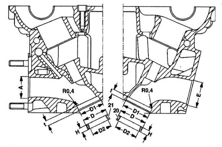
Valve seat dimensions
Valve seat installation details
| Inlet valve//Exhaust valve | |
| Nominal values, mm | |
| Hole diameter D1 | 36 H6//32 H6 |
| Seat diameter D | 36.10-36.12//32.10-32.12 |
| Repair values, mm | |
| Hole diameter D1 | 37.20 H6//33.20 H6 |
| Seat diameter D | 37.30//32.30 |
| Size «t» | 5.6-5.9 |
| Diameter D2 | 30//25.6 |
Piston ring performance
| Ring fit gaps in piston grooves, mm | |
| Characteristic | Meaning |
| Top compression ring | 0.20-0.40 |
| Lower compression ring | 0.20- 0.40 |
| Oil scraper ring | 0.20- 0.45 |
| Gaps in locks of rings, mm | |
| Top compression ring | 0.015-0.050 |
| Lower compression ring | 0.020- 0.040 |
| Oil scraper ring | 0.010- 0.045 |
Dimensions and weights of connecting rods and connecting rod bearings
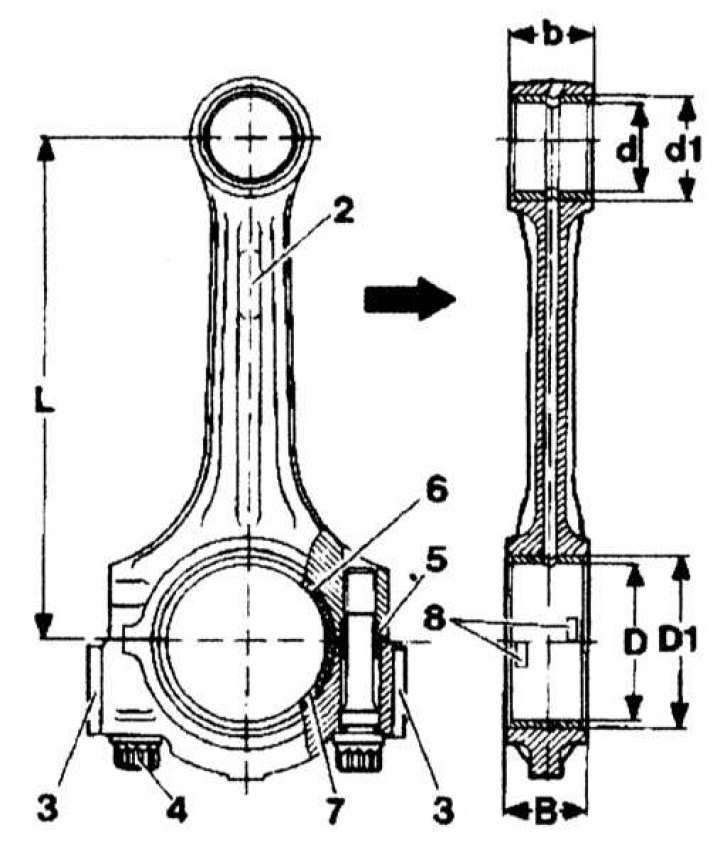
2 - Designation; 3 - Balancing weight; 4 - Bolt M9; 5 - Guide sleeve; 6 - Top liner; 7 - Lower insert; 8 - Mounting ears; Arrow - Direction of movement
| connecting rods | |
| Distance «L» between the centers of the connecting rod heads, mm | |
| M104.94 | 148.995-49.005 |
| M104.99 | 144.995-145.005 |
| Width «IN» the lower head of the connecting rod, mm | 21.948 - 22.000 |
| Width «b» the upper head of the connecting rod, mm | 21.948 - 22.000 |
| Diameter «D1» lower head without liners, mm | 51.600 - 51.619 |
| Diameter «d1» top head for bushing, mm | 24.500 - 24.571 |
| Inner diameter «d» bushings of the upper head of the connecting rod, mm | 22.007 - 22.013 |
| Play of a piston pin in the plug, mm | 0.013 - 0.018 |
| Permissible twisting of the connecting rod, mm | 0.015 |
| Permissible deviation from parallelism the upper head of the connecting rod and bushing, mm | 0.07 |
| Permissible weight difference of connecting rods, g | 4 |
| Crankshaft | |
| Diameters of connecting rod journals, mm / color marking of crank cheeks | |
| Nominal | 47.955 - 47.965/Unmarked |
| Nominal | 1 47.945 - 47.955/orange |
| Nominal | 2 47.935 - 47.945/Blue |
| 1st repair size | 47.700 - 47.715/- |
| 2nd repair size | 47.450 - 47.465/- |
| 3rd repair size | 47.200 - 47.215/- |
| 4th repair size | 46.950 - 46.965/- |
| Width of connecting rod journals, mm | |
| Nominal size | 27.958 - 28.042 |
| Repair size | until 28.300 |
| Connecting rod bearing shells | |
| Wall thickness, mm | |
| Nominal size | |
| red marking | 1.806 - 1.810 |
| Yellow marking | 1.810 - 1.814 |
| Blue marking | 1.814 - 1.818 |
| Rated 1 (not available as a spare part) | |
| red marking | 1.811 - 1.815 |
| Yellow marking | 1.815 - 1.819 |
| Blue marking | 1.819 - 1.823 |
| Rated 2 (not available as a spare part) | |
| red marking | 1.816 - 1.820 |
| Yellow marking | 1.820 - 1.824 |
| Blue marking | 1.824 - 1.828 |
| 1st repair size (Yellow marking) | 1.995 - 1.999 |
| 2nd repair size (Yellow marking) | 2.060 - 2.064 |
| 3rd repair size (Yellow marking) | 2.185 - 2.189 |
| 4th repair size (Yellow marking) | 2.310 - 2.314 |
Crankshaft and main bearing dimensions
| Control dimensions | |
| Permissible taper of the main and connecting rod journals of the crankshaft, mm | 0.002 |
| Permissible ovality at 54 mm length, mm | |
| Indigenous necks | 0.010 |
| crankpins | 0.010 |
| Permissible deviation of the axis of the installed liners, mm | 0.02 |
| Radius of inner fillet, mm | |
| Indigenous necks 1.9-2.1 | |
| Connecting rod journals 1.9-2.1 | |
| Repair dimensions | |
| Diameter of the main neck, mm / Color / Letter marking on the front of the crankshaft | |
| Nominal | |
| 57.960 - 57.965/Blue/B | |
| 57.955 - 57.960/Yellow/G | |
| 57.950 - 57.955/Red/R | |
| Rated 1 | |
| 57.945 - 57.950/White/W | |
| 57.940 - 57.845/Purple/V | |
| 1st repair size | 57.705 - 57.715/-/- |
| 2nd repair size | 57.450 - 57.465/-/- |
| 3rd repair size | 57.205 - 57.215/-/- |
| 4th repair size | 57.955 - 57.965/-/- |
Letter marking
Note. The color marking is applied to the counterweights No. 8 and 9, the letter designation is on the front of the crankshaft.
| Width of the main neck, mm / Color / | |
| Nominal size | |
| 24.500 - 24.533/-/0 | |
| Rated 1 | |
| 24.600 - 24.633/Red/1 | |
| 1st repair size | 24.700 - 24.733/-/- |
| 2nd repair size | 24.900 - 24.933/-/- |
| 3rd repair size | 25.000 - 25.033/-/- |
| 4th repair size | -/-/- |
Selection of the thickness of the main bearing shells
| Nominal size (Main bearing journal hole diameter 58.00 mm) | |
| blue label (index 52) | |
| Upper liner thickness, mm | 2.255-2.260 |
| Thickness of the lower insert, mm | 2.255-2.260 |
| yellow label (index 54) | |
| Upper liner thickness, mm | 2.260-2.265 |
| Thickness of the lower insert, mm | 2.260-2.265 |
| red label (index 56) | |
| Upper liner thickness, mm | 2.265-2.270 |
| Thickness of the lower insert, mm | 2.265-2.270 |
| Nominal size 1 (Main bearing journal hole diameter 58.00 mm) | |
| white and blue label (index 57) | |
| Upper liner thickness, mm | — |
| Thickness of the lower insert, mm | 2.263-2.268 |
| white and yellow label (index 58) | |
| Upper liner thickness, mm | — |
| Thickness of the lower insert, mm | 2.268-2.273 |
| White-red label (index 60) | |
| Upper liner thickness, mm | — |
| Thickness of the lower insert, mm | 2.273-2.278 |
| 1st repair size (Main bearing journal hole diameter 57.75 mm) | |
| blue label (index 52) | |
| Upper liner thickness, mm | 2.375-2.380 |
| Thickness of the lower insert, mm | 2.375-2.380 |
| yellow label (index 54) | |
| Upper liner thickness, mm | 2.380-2.385 |
| Thickness of the lower insert, mm | 2.380-2.385 |
| 2nd repair size (Main bearing journal hole diameter 57.50 mm) | |
| blue label (index 52) | |
| Upper liner thickness, mm | 2.500-2.505 |
| Thickness of the lower insert, mm | 2.500-2.505 |
| Nominal insert width, mm | 19.979 - 20.000 |
| Diameter of beds of main bearings of a cranked shaft, mm | |
| Bearings No. 1, 5, 7 | |
| 1 punching | 62.500-62.505 |
| 2 punches | 62.506-62.513 |
| 3 punches | 62.513-62.519 |
| Bearings No. 2, 3, 4, 6 | |
| 2 punches | 62.500-62.506 |
| 3 punches | 62.506-62.519 |
Dimensions and designations of cylinders and pistons
| Cylinder//piston diameters, mm | |
| Nominal size (89.9 mm) | |
| Tolerance group A marking | 89.900 -89.906//89.873 - 89.879 |
| Tolerance group marking X | 89.906 - 89.912//88.878 - 89.886 |
| Tolerance group marking B | 89.912 - 89.918//89.885 - 89.891 |
| 1st repair size (+ 0.25 mm) | |
| Tolerance group A marking | 90.150 - 90.156//90.123 - 90.129 |
| Tolerance group marking X | 90.156 - 90.162//90.128 - 90.136 |
| Tolerance group marking B | 90.162 - 90.168//90.135 - 90.141 |
| 2nd repair size (+ 0.5 mm) | |
| Tolerance group A marking | 90.400 - 90.406//90.373 - 90.379 |
| Tolerance group marking X | 90.406 - 90.412//90.378 - 90.386 |
| Tolerance group B marking | 90.412 - 90.418//90.385 - 90.391 |
Note. Marking (except AMG engines) applied to the convex part of the piston and embossed on the mating surface of the cylinder block.
Block dimensions
| Height, mm | 282.25 -282.35 |
| Minimum allowable height after processing1), mm | 281.95 |
| Permissible roughness of the mating surface of the cylinder block, mm | |
| Upper | 0.03 |
| Lower | 0.04 |
| 1) After processing the cylinder block, a height change of no more than 0.4 mm is allowed. | |
M119 series engines
Camshaft bearing dimensions
| Diameter of beds of bearings of camshafts in a head of the block of cylinders, mm | |
| Nominal size | 28.000 28.021 |
| Repair size | 28.500 26.521 |
| Diameter of a neck of the bearing of a camshaft, mm | |
| Nominal | 27.960 2.947 |
| Repair | 28.447 28.460 |
| Backlash in camshaft bearings, mm | |
| Radial | 0.053-0.061 |
| Axial | 0.050-0.150 |
Valve guide dimensions

Non-ferrous guide bush (M104.990 engines of the first version)
| Nonferrous bushings (only M119.97 engines) | |
| Diameters of openings in a head of the block of cylinders, mm | |
| Nominal size | 13.50-13.51 |
| 1st nominal size | 13.53 |
| Repair size | 13.70 |
| Outer diameter of the guide sleeve, mm / color coding | |
| Nominal size | 13.51-13.53/- |
| 1st nominal size | |
13.52-13.53/grey green | |
13.54-13.55/Taupe | |
| Repair size | 13.71-13.72/Red |
| Outer diameter of the guide sleeve, mm / color coding | |
| Guide inner diameter, mm | |
| Inlet and outlet valves | 7.000-7.015 |
| Outer diameter of the guide sleeve, mm / color coding | |
| Length «L» bushings, mm | |
| Inlet valve | 35.5 |
| Exhaust valve | 37.9 |
| Distance «A» (inlet valve), mm | 2.7-2.9 |
| Distance «b» (intake and exhaust valves), mm | 5.4-5.6 |
| Distance «With» (intake and exhaust valves), mm | 10.8-11.2 |
| Sintered bushings (all engines of the M119 series) | |
| Hole diameter in the cylinder head, mm | |
| Nominal size | 12.50-12.51 |
| 1st nominal size | 12.53 |
| Repair size | 12.70 |
| Outer diameter of the guide sleeve, mm / Color coding | |
| Nominal size | 12.54-12.55/- |
| 1st nominal size | 12.56-12.57/Grey |
| Repair size | 12.74-12.75/Red |
| Guide sleeve inner diameter, mm | |
| Inlet and outlet valves | 7.000-7.015 |
| Length «L» guide sleeve, mm | |
| Inlet and outlet valves | 37.5 |
| Distance «A», mm | — |
| Distance «b» (intake and exhaust valves), mm | 5.4-5.6 |
| Distance «With» (intake and exhaust valves), mm | 10.2-10.4 |
Valve seat dimensions
M119.970 engines
| Nominal dimensions | |
| Diameter «D1» holes in the cylinder head, mm | |
| intake valves | 39 H6 |
| exhaust valve | 34 H6 |
| Diameter «D» seats, mm | |
| intake valves | 39.10-39.09 |
| exhaust valves | 34.10-34.09 |
| Repair dimensions | |
| Diameter «D1» holes in the cylinder head, mm | |
| intake valves | 40.20 H6 |
| exhaust valves | 35.20 H6 |
| Diameter «D» seats, mm | |
| intake valves | 40.30 |
| Released valves | 35.30 |
| Size «t» (intake and exhaust valves), mm | 7.8-7.9 |
| Diameter «D2», mm | |
| intake valves | 38.47 |
| exhaust valves | 33.47 |
M119.971/980/982 engines
| Nominal dimensions | |
| Diameter «D1» holes in the cylinder head, mm | |
| intake valves | 36 H6 |
| exhaust valves | 34 H6 |
| Diameter «D» seats, mm | |
| intake valves | 36.10-36.09 |
| exhaust valves | 34.10-34.09 |
| Repair dimensions | |
| Diameter «D1» holes in the cylinder head, mm | |
| intake valves | 37.20 H6 |
| exhaust valves | 35.20 H6 |
| Diameter «D» seats, mm | |
| intake valves | 37.30 |
| exhaust valves | 35.30 |
| Size «t» (intake and exhaust valves), mm | 7.8 - 7.9 |
| Diameter «D2», mm | |
| intake valves | 35.47 |
| exhaust valves | 33.47 |
Dimensions and designations of cylinders and pistons

A - Longitudinal direction
B - Lateral direction
a - The upper point of the stroke of the upper compression ring
b — bottom dead center
c - The lower point of the stroke of the oil scraper ring
1, 2, 3 - Measurement points
M119.960/970/972/974 series engines
| Piston//cylinder diameters, mm | |
| Nominal size (96.5 mm) | |
| Designation 0 (index 52) | 96.483-96.493// 96.498-96.503 |
| Designation 0+ (Index 53) | 96.488-96.498// 96.503-96.508 |
| Designation 1 (Index 54) | 96.493-96.503// 96.508-96.513 |
| Designation 1+ (Index 55) | 96.498-96.508// 96.513-96.518 |
| Designation 2 (Index 56) | 96.503-96.513// 96.518-96.523 |
| 1st repair size (+0.5 mm) | |
| Designation 0 | 96.983-96.993//96.998-97.003 |
| Designation 1 | 96.993-97.003//97.008-97.013 |
| Designation 2 | 97.003-97.013//97.018-97.023 |
| 2nd repair (+1.0 mm) | |
| Designation 0 | 97.483-97.493//97.498-97.503 |
| Designation 1 | 97.493-97.503//97.508-97.513 |
| Designation 2 | 97.503-97.513//97.518-97.523 |
M119.980/982/970/972/974 series engines
| Piston//cylinder diameters, mm | |
| Nominal size (96.5 mm) | |
| Designation A (index 52) | 96.482-96.495// 96.500-96.508 |
| Designation B (index 54) | 96.491-96.504// 96.508-96.516 |
| Designation C (index 56) | 96.499-96.512// 96.516-96 524 |
| 1st repair (+0.5 mm) | |
| Designation A | 96.982-96.995//97.000-97.008 |
| Designation B | 96.991-97.004//97.008-97.016 |
| Designation | С 96.999-97.012//97.016-97.024 |
| 2nd repair (+1.0 mm) | |
| Designation A | 97.482-97.495//97.000-97.508 |
| Designation B | 97.491-97.504//97.508-97.516 |
| Designation C | 97.499-97.512//97.516-97.524 |
M119.971/975/981/985 engines (digital designation)
| Piston//cylinder diameters, mm | |
| Nominal size (92.0 mm) | |
| Designation 0 (index 52) | 91.983-91.993// 91.998-91.003 |
| Designation 0+ (index 53) | 91.988-91.998// 92.003-92.008 |
| Designation 1 (index 54) | 91.993-92.003// 92.008-92.013 |
| Designation 1+ (index 55) | 91.998-92.008// 92.013-92.018 |
| Designation 2 (index 56) | 92.003-92:013// 92.018-92.023 |
| 1st repair (+0.5 mm) | |
| Designation 0 | 92.483-92.493//92.498-92.503 |
| Designation 1 | 92.493-92.503//92.508-92.513 |
| Designation 2 | 92.503-92.513//92.518-92.523 |
| 2nd repair (+1.0 mm) | |
| Designation 0 | 92.983-92.993//92.998-93.003 |
| Designation 1 | 92.993-93.003//93.008-93.013 |
| Designation 2 | 93.003-93.013//93.018-93.023 |
M119.971/975/981/985 engines (letter designation)
| Piston//cylinder diameters, mm | |
| Nominal size (96.5 mm) | |
| Designation A (index 52) | 91.982-91.995// 92.000-92.008 |
| Designation B (index 54) | 91.991-92.004// 92.008-92.016 |
| Designation C (index 56) | 91.999-92.012// 92.016-92.024 |
| 1st repair (+0.5 mm) | |
| Designation A | 92.482-92.495//92.500-92.508 |
| Designation B | 92.491-92.504//92.508-92.516 |
| Designation C | 92.499-92.512//92.516-92.524 |
| 2nd repair (+1.0 mm) | |
| Designation A | 92.982-92.995//93.000-93.008 |
| Designation B | 92.991-93.004//93.008-93.016 |
| Designation C | 92.999-93.012//93.016-93.024 |
Connecting rod dimensions

connecting rods
| Distance «L» between the centers of the connecting rod heads, mm | 154.450-154.550// 148.950-149.050 |
| Width «IN» the lower head of the connecting rod, mm | 24.857-24.890//24.857-24.890 |
| Width «b» the upper head of the connecting rod, mm | 27.900-28.000//21.900-22.100 |
| Diameter «D» lower head without liners, mm | 51.600-51.619//51.600-51.619 |
| Diameter «d1» top head for bushing, mm | 26.007-26.013//24.007-24.013 |
| Inner diameter «d» top head bushings connecting rod, mm | 29.000-29.021//27.000-27.210 |
| Play of a piston pin in the plug, mm | 0.007-0.018 |
Dimensions of the crankshaft, main and connecting rod bearings
Pilot bearing motors
| Diameter of a neck of a cranked shaft, mm | |
| Nominal | |
| Blue marking | 63.965 |
| Yellow marking | 63.960 |
| red marking | 63.955 |
| 1st repair | 63.700 |
| 2nd repair size | 63.450 |
| 3rd repair size | 63.200 |
| 4th repair size | 62.950 |
| Main journal width with mounting bearing, mm | |
| Nominal size | 27.021 |
| Maximum allowable size | 27.50 |
| Diameter of a neck of a cranked shaft, mm | |
| Nominal | 47.955 |
| 1st repair | 47.705 |
| 2nd repair size | 47.455 |
| 3rd repair size | 47.205 |
| 4th repair size | 46.955 |
| Width of the main neck, mm | |
| Nominal size | 50.100 |
| Maximum allowable size | 50.30 |
| Diameter of holes for main bearings, mm | |
| Blue marking | 68.486 |
| Yellow marking | 68.492 |
| red marking | 68.500 |
| Diameter of holes for connecting rod bearings, mm | 51.619 |
| Permissible ovality and taper of main and connecting rod journals of the crankshaft, mm | 0.01 |
| Radial clearance in main bearings, mm | |
| new shaft | 0.021 - 0.045 |
| Limit value | 0.09 |
| Radial clearance in connecting rod bearings, mm | |
| new shaft | 0.030 - 0.055 |
| Limit value | 0.080 |
| Axial backlash of a cranked shaft, mm | |
| new shaft | 0.10 - 0.22 |
| Limit value | 0.30 |
| Axial play of connecting rods, mm | |
| new shaft | 0.22 - 0.38 |
| Limit value | 0.50 |
Correspondence of color and dot marking of liners of main bearings and cylinder block
| Options | Marking | ||
| Dot marking on cylinder block | 1 point | 2 points | 3 points |
| Color coding on bearing caps/block casting | Blue | Yellow | Red |
| Color coding of top liners | Blue | Yellow | Red |
| Color coding of lower liners | Blue | Yellow | Red |
Thrust ring motors
| Crankshaft journal diameter//thickness of thrust half rings, mm | |
| Nominal size | |
| Blue marking | 63.960-63.965//2.20 |
| Yellow marking | 63.955-63.960//2.25 |
| red marking | 63.950-63.955//2.30 |
| 1st nominal size | 63.945-63.950 63.940-63.945 63.935-63.940 |
| Crankshaft journal width, mm | 27.000-27.033 |
| Diameter of a neck of a cranked shaft, mm | 47.955-47.965 |
| Crankshaft journal width, mm | 50.000/50.100 |
| Diameter of holes for main bearings, mm | |
| Blue marking | 68.480-68.486 |
| Yellow marking | 68.986-68.492 |
| red marking | 68.492-68.500 |
| Connecting rod hole diameter bearings, mm | 51.600-51.619 |
| Permissible ovality and taper of main and connecting rod journals of the crankshaft, mm | 0.01 |
| Radial clearance in main bearings, mm | |
| new shaft | 0.021 - 0.045 |
| Limit value | 0.09 |
| Radial clearance in connecting rod bearings, mm | |
| new shaft | 0.030 - 0.055 |
| Limit value | 0.080 |
| Axial backlash of a cranked shaft, mm | |
| new shaft | 0.10 - 0.22 |
| Limit value | 0.30 |
| Axial play of connecting rods, mm | |
| new shaft | 0.22 - 0.38 |
| Limit value | 0.50 |
Correspondence of color and dot marking of liners of main bearings and cylinder block
| Options | Marking | ||
| Dot marking on cylinder block | 1 point | 2 points | 3 points |
| Color coding on bearing caps/block casting | Blue | Yellow | Red |
| Color coding of top liners | Blue | Yellow | Red |
| Color coding of lower liners | Blue | Yellow | Red |
M120 series engines
Code designations of camshafts
| M120.980 series motors according to No. 010 822 | |
| Right intake camshaft | 29 |
| Left intake camshaft | 30 |
| Right exhaust camshaft | 27 |
| Left exhaust camshaft | 28 |
| M120.980 series engines with No. 010 823 and M120.982 | |
| Right intake camshaft | 33 |
| Left intake camshaft | 34 |
| Right exhaust camshaft | 31 |
| Left exhaust camshaft | 32 |
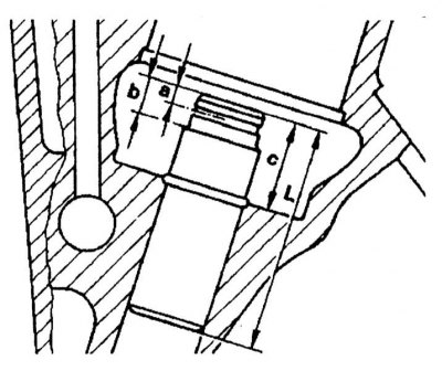
Valve guide dimensions and installation details
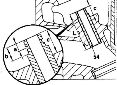
Valve guide installation details
| Nonferrous bushings | |
| Guide sleeve inner diameter, mm | |
| Inlet valve | 7.000 - 7.015 |
| Exhaust valve | 8.000 - 8.015 |
| Guide sleeve length «L», mm | 37.5 |
| Preload in the cylinder head | 0.029 - 0.051 |
| Retaining ring | Not installed |
| Distance «a» | 2.7 - 2.9 |
| Distance «b» | 5.4 - 5.6 |
| Distance «c» | 8.2 - 8.6 |
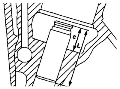
| Metallized bushings | |
| Guide sleeve inner diameter, mm | |
| Inlet valve | 7.000 - 7.015 |
| Exhaust valve | 7.000 - 7.015 |
| Guide sleeve length «L», mm | 37.5 |
| Preload in the cylinder head | 0.029 - 0.051 |
| Retaining ring | Installed |
| Distance «a» | — |
| Distance «b» | — |
| Distance «c» | 10.2 - 10.4 |
Dimensions and designations of cylinders and pistons
| Cylinder//piston diameters, mm | |
| Nominal size (89 mm) | |
| Group1) 0 | 89.000 - 89.008//88.978 - 88.988 |
| Group 1 | 89.008 - 89.016//88.988 - 88.998 |
| Group 2 | 89.016 - 89.024//88.998 - 89.008 |
| 1st repair size (+ 0.352) mm) | |
| Group 0 | 89.350 - 89.358 // 89.328 - 89.338 |
| Group 1 | 89.358 - 89.366 // 89.338 - 89.348 |
| Group 2 | 89.361 - 89.374 // 89.348 - 89.358 |
| 2nd repair size (+0.72) mm) | |
| Group 0 | 89.700 - 89.708 // 89.678 - 89.688 |
| Group 1 | 89.708 - 89.710 // 89.688 - 89.698 |
| Group 2 | 89.716 - 89.724 // 89.698 - 89.708 |
| 1) The group number on new engines is stamped on the mating surface of the cylinder block, the next cylinder | |
| 2) The group number is painted on the piston skirt and is also embossed on the side of the piston skirt | |
Connecting rod dimensions

| Size «l», mm | 153.95 - 154.05 |
| Width of the lower connecting rod head «IN», mm | 21.948 - 22.000 |
| Upper conrod head width «b», mm | 19.90 - 20.10 |
| Connecting rod bore diameter «D1», mm | 51.600 - 51.619 |
| Connecting rod bore diameter «d1», mm | 24.500 - 24.521 |
| Connecting Rod Bushing Inner Diameter «d», mm | 22.007 - 22.013 |
| Gap of landing of a piston pin in the plug of a rod, mm | 0.013 - 0.018 |
| Permissible weight difference of connecting rods assy, g | 4 |
Dimensions of the crankshaft, main and connecting rod bearings
| Diameter of the main journal of the crankshaft / / thickness of the thrust gasket of the installation bearing, mm | |
| Nominal size | 57.960//2.15 57.955//2.20 57.950//2.25 |
| 1st nominal size | 57.945//2.35 57.940//2.40 57.935 |
| 1st repair size | 57.700 |
| 2nd repair size | 57.450 |
| 3rd repair size | 57.200 |
| Diameter of connecting rod journals, mm | |
| Nominal size | 47.955 |
| 1st repair size | 47.705 |
| 2nd repair size | 47.455 |
| 3rd repair size | 47.205 |
| Width of connecting rod journals, mm | 24.225 |
| Diameter of beds of main bearings, mm | 62.500 |
| Diameter of connecting rod bearing beds, mm | 61.600 |
| Core inner diameter bearings, mm | 23.500 |
| Connecting rod width, mm | 22.000 |
| Permissible ovality and taper of bearing beds | 0.02 |
| Radial clearance, mm | |
| main bearings | 0.026 - 0.050 |
| Connecting rod bearings | 0.020 - 0.058 |
| Axial backlash of a cranked shaft, mm | 0.100 - 0.254 |
| Axial play of connecting rods, mm | 0.225 - 0.391 |
Correspondence of color and dot marking of liners of main bearings and cylinder block
| Options | Meaning | ||||
| Dot marking on cylinder block | 1 point | 2 points | 3 points | — | — |
| Color coding on bearing caps | Blue | Yellow | Red | — | — |
| Color coding on the crankshaft | Blue | Yellow | Red | White | Violet |
| Color coding of top liners | Blue | Yellow | Red | — | — |
| Color coding of lower liners | Blue | Yellow | Red | White | Violet |
| Letter marking on main bearing journals | IN | G | R | W | V |
| Valid diameter numbers on main journals | 35-39 | 40-44 | 45-49 | 50-54 | 55-60 |
OM603 series motors
Connecting rod dimensions

1 - Connecting rod; 2 - Connecting rod cover; 3 - Bushing; 4 - Guide grooves; 5 - Connecting rod bolt; 6 - Balancing weights; 7 - Identification field (turbocharged models); 8 - Grooves for inserts installation; 9 - Oil channel (turbocharged models); 10 - Oil channel (non-turbo models); 11 - Identification field (non-turbo models); b - Width of the upper head of the connecting rod; B - Width of the lower head of the connecting rod; d - Inner diameter of the bushing of the upper head of the connecting rod; d1 - Outer diameter of the bushing of the upper head of the connecting rod; D1 - Diameter of the hole of the lower head of the connecting rod; L - distance between the centers of the holes of the connecting rod heads
| Size «L», mm | 144.97 - 145.03 |
| Connecting Rod Width «IN», mm | 21.948 - 22.000 |
| Connecting rod bore diameter «D1» | 51.600 - 51.614 |
| Maximum allowable ovality and taper of the hole, mm | 0.02 |
| Connecting Rod Bushing Inner Diameter «d», mm | 28.018 - 28.024 |
| Sleeve outer diameter, mm | 30.575 - 30.600 |
| Connecting rod bore diameter (under the sleeve) «d1», mm | 30-500 - 30-525 |
| Play of landing of a piston pin in the plug of a rod, mm | 0.007 - 0.018 |
Cylinder dimensions
| Cylinder diameter, mm | |
| Nominal | 89.0 |
| Size group A | 89.000 - 89.006 |
| Size group X | 89.007 - 89.012 |
| Size group B | 89.013 - 89.018 |
| Permissible deviation of the cylinder diameter in the longitudinal and transverse directions, mm | 0.20 |
| Permissible taper, mm | 0.007 |
| Permissible ovality, mm | 0.07 |
| Wear limit, mm | 0.05 |
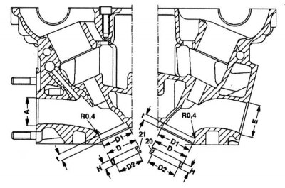
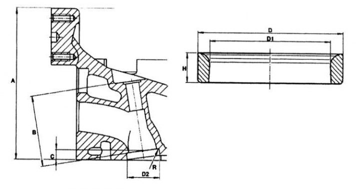
The dimensions of the holes in the cylinder block for the installation of liners
D, D1 - Diameters for sleeve flanges
D2 - Sleeve diameter
T - Sleeve length
T1 - Seat depth of the sleeve
| Diameter «D2» under the sleeve in the block cylinders, mm | 91.500 - 91.535 |
| Diameter «D1» under the collar of the sleeve in the block of cylinders, mm | 92.00 - 92.20 |
| Diameter «D» under the collar of the sleeve in the block of cylinders, mm | 94.15 - 94.25 |
| Sleeve length «T», mm | 231.0 - 231.2 |
| Sleeve seating depth «T1», mm | 1.0 - 1.2 |
| Chamfer Width «M», mm | 35 |
Dimensions of the crankshaft, main and connecting rod bearings
| Main journal diameter, mm | |
| Nominal size | 57.940 - 57.965 |
| 1st repair size | 57.700 - 57.715 |
| 2nd repair size | 57.450 - 57.465 |
| 3rd repair size | 57.200 - 57.215 |
| 4th repair size | 56.950 - 56.965 |
| Main journal diameter, mm | |
| Nominal size | 47.940 - 47.965 |
| 1st repair size | 47.700 - 47.715 |
| 2nd repair size | 47.450 - 47.465 |
| 3rd repair size | 47.200 - 47.215 |
| 4th repair size | 46.950 - 46.964 |
| Mounting width of main journals, mm | |
| Nominal size | 24.500 - 24.533 |
| 1st repair size | 24.600 - 24.633 |
| 2nd repair size | 24.700 - 24.733 |
| 3rd repair size | 24.900 - 24.933 |
| 4th repair size | 25.000 - 25.033 |
| Hole diameter for crankshaft, mm | 62.500 - 62.519 |
| The width of the hole for the crankshaft with liners installed, mm | 19.979 - 20.000 |
| Permissible ovality and taper of the beds of the liners of the main bearings, mm | 0.02 |
| Working clearances of main bearings, mm | |
| New | 0.03 - 0.05 |
| Permissible | 0.08 |
| Axial backlash of a cranked shaft, mm | |
| New | 0.10 - 0.25 |
| Permissible | 0.3 |
| Radial runout of the crankshaft, mm | 0.020 - 0.065 |
| Standard crankshaft shells for bearing caps diameter | 58 mm |
| Repair diameter (color - blue), mm | 52 |
| Repair diameter (yellow color), mm | 54 |
| Repair diameter (yellow color), mm | 54 |
| Insert thickness, mm | 2.260 - 2.265 |
| Repair diameter (color - red), mm | 56 |
| Insert thickness, mm | 2.265 - 2.270 |
| Repair diameter (White color), mm | 57 |
| Insert thickness, mm | 2.270 - 2.275 |
| Repair diameter (color magenta), mm | 58 |
| Insert thickness, mm | 2.275 - 2.280 |
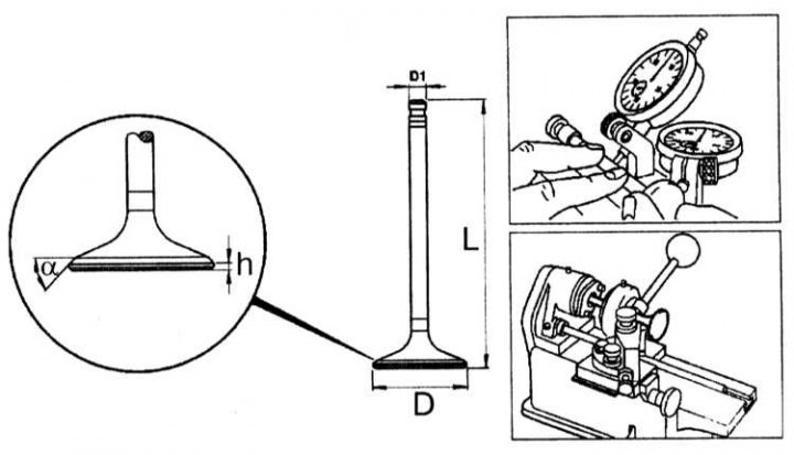
OM606 series motors
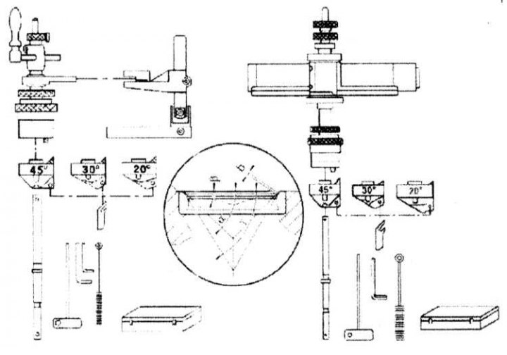
Valve sizes
1 - Setting marks for bringing the engine to the TDC position of the end of the compression stroke of the piston of the first cylinder
2 - Blocking the intake camshaft with a rod
3 - Make sure the 1.5mm holes in the sprockets line up correctly
4 - For fastening the camshaft sprockets, disposable bolts are used, which must be replaced without fail
5 - Assembling the chain tensioner
6 - When removing / installing the injection pump, the crankshaft should be brought to the position 14°+ 05°after the TDC of the piston of the first cylinder
7 - The injection pump sprocket bolt has a left-hand thread.
8 - Locking tool
| Valve disc diameter «D», mm | |
| Inlet | 25.90 - 26.10 |
| High school graduation | 28.90 - 29.10 |
| Height of the cylindrical part (girdle) valve discs «h», mm | 1.0 - 1.2 |
| Valve seat angle | 45° 15' |
| Valve stem diameter «D1», mm | |
| Inlet | 6.955 - 6.97 |
| High school graduation | 5.955 - 5.97 |
| Full valve length «L», mm | |
| Inlet | 105.5 - 105.9 |
| High school graduation | 105.2 - 105.9 |
| The width of the working chamfer of the valve seat, mm | 1.9 |
| Displacement of the axis of the valve seat relative to the rod, mm | 0.03 |
| Designation on the end of the valve stem | |
| Inlet | A 606 13 |
| High school graduation | E 606 11 |
Valve guide dimensions

Valve guide installation details
| Hole diameter in the cylinder head, mm | |
| Nominal | 12.50 - 12.51 |
| 1st Nominee | 12.53 |
| 1st repair | 12.70 |
| Outer diameter of the guide sleeve, mm | |
| Nominal | 12.54 - 12.55 |
| 1st Nominee (color: gray) | 12.56 - 12.57 |
| 1st repair (color: red) | 12.74 - 12.75 |
| Guide sleeve inner diameter, mm | |
| Inlet valve | 6.000 - 6.015 |
| Exhaust valve | 6.000 - 6.015 (until 11.94) 7.000 - 7.015 (from 11.94) |
| Guide sleeve length «L», mm | 37.5 |
| Preload fit in the head of the block cylinders, mm | 0.029 - 0.051 |
| Size «A» | — |
| Size «b» | — |
| Size «With» | 10.2 - 10.04 |
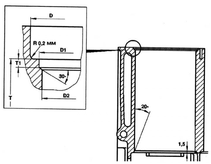
Valve seat dimensions
Milling and grinding of valve seats
Valve seat installation details
| Guide sleeve inner diameter, mm | |
| Valve seat bevel width «b», mm | |
| Inlet valve | 1.0 - 1.5 |
| Exhaust valve | 0.8 - 1.5 |
| Valve seat chamfer angle b | 45° 15' |
| Correction angle in | |
| Inlet valve | 15° 15' |
| Exhaust valve | 25° 15' |
| Maximum ovality of the valve seat, mm | 0.03 |
| Distance from valve stem end to camshaft bearing «T», mm | 23.7 - 24.2 |
| Hole depth «WITH» under the valve seat in the cylinder head, mm | |
| standard ring | |
| Inlet valve | 7.94 - 8.04 |
| Exhaust valve | 7.924 - 8.02 |
| repair ring | |
| Inlet valve | 8.14 - 8:24 |
| Exhaust valve | 8.12 - 8.23 |
| Radius «R», mm | |
| Inlet valve | 0.2 - 0.4 |
| Exhaust valve | 0.2 - 0.4 |
| Diameter «D2» holes for the valve seat, mm | |
| nominal size | |
| Inlet valve | 30.060 - 30.070 |
| Exhaust valve | 28.000 - 28.013 |
| Repair size | |
| Inlet valve | 30.250 - 30.266 |
| Exhaust valve | 28.250 - 28.263 |
| Valve overlap, mm | |
| Inlet valve | 0.2 - 0.4 |
| Exhaust valve | 0.2 - 0.4 |
| Valve seat height «H», mm | |
| nominal size | |
| Inlet valve | 5.6 |
| Exhaust valve | 5.6 |
| 1st repair size | |
| Inlet valve | 5.6 |
| Exhaust valve | 5.6 |
| Outside diameter «D» valve seats, mm | |
| nominal size | |
| Inlet valve | 30.000 - 30.013 |
| Exhaust valve | 27.97 - 28.07 |
| 1st repair size | |
| Inlet valve | 30.31 - 30.32 |
| Exhaust valve | 28.31 - 28.32 |
Connecting rod dimensions
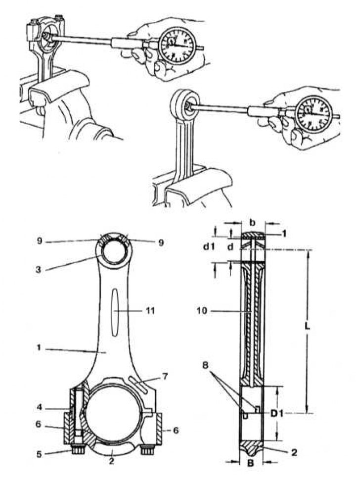
1 - Connecting rod; 2 - Connecting rod cover; 3 - Bushing; 4 - Guide grooves; 5 - Connecting rod bolt; 6 - Balancing weights; 7 - Identification field (turbocharged models); 8 - Grooves for inserts installation; 9 - Oil channel (turbocharged models); 10 - Oil channel (non-turbo models); 11 - Identification field (non-turbo models); b - Width of the upper head of the connecting rod; B - Width of the lower head of the connecting rod; d - Inner diameter of the bushing of the upper head of the connecting rod; d1 - Outer diameter of the bushing of the upper head of the connecting rod; D1 - Diameter of the hole of the lower head of the connecting rod; L - distance between the centers of the holes of the connecting rod heads
| Distance between connecting rod centers heads «L», mm 1 | 48.7 - 149.3 |
| Upper width «b» and bottom «IN» connecting rod heads, mm | 21.48 - 22.00 |
| Diameter «D1» lower head connecting rod, mm | 51.600 - 51.614 |
| Permissible ovality and taper of the hole of the lower head of the connecting rod, mm | 0.02 |
| Permissible connecting rod twist per 100 mm length, mm | 0.1 |
| Permissible deviation difference from parallelism between heads connecting rod per 100 mm of connecting rod length, mm | 0.045 |
| Upper sleeve inner diameter connecting rod heads «d», mm | 28-018 - 28.024 |
| Sleeve outer diameter, mm | 30.575 - 30.600 |
| Diameter for the bushing in the upper head of the connecting rod «d1», mm | 30.500 - 30.525 |
| Piston pin clearance in bushing the upper head of the connecting rod, mm | 0.007- 0.008 |
| Max protrusion (Rz) bushings connecting rod out, microns | 5 |
| The maximum allowable difference in the weight of the connecting rods, g | 2 |
Dimensions of holes in the cylinder block for the installation of liners, mm
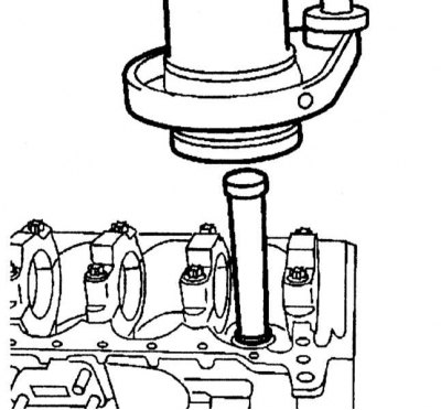
Extraction of the sleeve
| Diameter «D2» under the sleeve in the glare of cylinders, mm | 9.000 - 90.535 |
| Diameter «D1» under the collar of the sleeve in the cylinder block, mm | 90.55 - 90.65 |
| Diameter «D» under the collar of the sleeve in the cylinder block, mm | 92.65 - 92.75 |
| Sleeve length «T», mm | 231.0-231.2 |
| Sleeve seating depth «T1», mm | 1.0 - 1.2 |
Cylinder dimensions
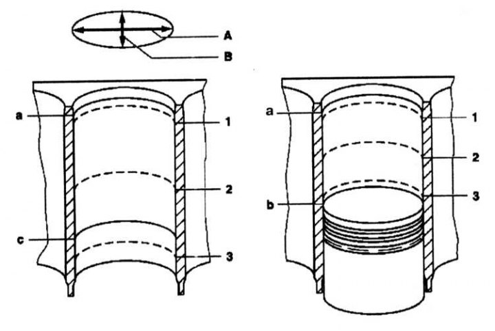
A - Longitudinal direction
B - Lateral direction
a - The upper point of the stroke of the upper compression ring
b — bottom dead center
c - The lower point of the stroke of the oil scraper ring
1, 2, 3 - Measurement points
| Diameter, mm | |
| Nominal | 87.0 |
| Size group A | 87.000 - 87.006 |
| Size group X | 87.007 - 87.012 |
| Size group B | 87.013 - 87.018 |
| Permissible limit of the cylinder in the longitudinal and transverse directions, mm | 0.20 |
| Permissible taper of cylinders new block, mm | 0.000 - 0.014 |
| Wear limit, mm | 0.05 |
| Permissible ovality of cylinders, mm | 0.07 |
Crankshaft dimensions
| Hole diameter under the crankshaft, mm | 62.500 - 62.519 |
| Crankshaft bore width with installed liners, mm | 19.979 - 20.000 |
| Permissible ovality and taper bed liners indigenous crankshaft bearings, mm | 0.02 |
| Working clearance in main bearings, mm | |
| New | 0.03 - 0.05 |
| Maximum allowable | 0.08 |
| Axial backlash of a cranked shaft, mm | |
| New | 0.10 - 0.25 |
| Maximum allowable | 0.3 |
| Radial runout of the crankshaft, mm | 0.020 - 0.065 |
| Rated crankshaft shells for 58 mm diameter bearing caps | |
| Repair diameter (color - blue), mm | 52 |
| Insert thickness, mm | 2.255 - 2.260 |
| Repair diameter (yellow color), mm | 54 |
| Insert thickness, mm | 2.260 - 2.265 |
| Insert thickness, mm | 2.265 - 2.270 |
| Repair diameter (White color), mm | 57 |
| Insert thickness, mm | 2.270 - 2.275 |
| Repair diameter (color - purple), mm | 58 |
| Insert thickness, mm | 2.275 - 2.280 |
| Liners of the 1st repair size of the crankshaft for bearing caps with a diameter of 57.70 mm | |
| Insert thickness, mm | 2.37 |
| Liners of the 2nd repair size of the crankshaft for bearing caps with a diameter of 57.40 mm | |
| Insert thickness, mm | 2.50 |
| Liners of the 3rd repair size of the crankshaft for bearing caps with a diameter of 57.20 mm | |
| Insert thickness, mm | 2.62 |
| Liners of the 4th repair size of the crankshaft for bearing caps with a diameter of 56.90 mm | |
| Insert thickness, mm | 2.75 |
Tightening force of threaded connections, Nm
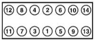
The procedure for tightening the cylinder head bolts on models with gasoline engines
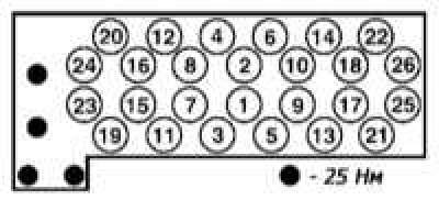
Tightening procedure for cylinder head bolts on models with diesel engines
| Cylinder head bolts | |
| Petrol models (length to base heads no more than 162.7 mm) | 55LFm, +90°, +90° |
| S300 TDI up to 01.89 g (length to the base of the heads no more than 83.6, 105.6 and 118.6 mm) | 25LFm, +40LFm, wait 10 min, +90°, +90° |
| S300 TDI after 01.89 (length to base heads no more than 82, 104 and 117 mm) | 15LFm, +35LFm, +90°, wait 10 min, +90° (М8 25НЧм) |
| Main bearing cap bolts | |
| S280, S320 (length to the base of the head no more than 63.8 mm) | 55LFm, +90°, -100° |
| S420, S500 | 25LFm, +50LFm |
| S300 TDI | M11: 55LFm, +90°, M12: 90LFm |
| S600 | M8: 30NCm, M10: 50NCm |
| Connecting rod bearing cap bolts | |
| S280, S320 (length to the base of the head no more than 52.9 mm) | 30+90° |
| S420, S500, S600 | 45LFm, +90°, -100° |
| S300 TDI | 40LFm, +90°, -100° |
| Flywheel/drive plate bolts S280, S320, S420 (unthreaded diameter no more than 8.1 mm for flywheel, 8.0 mm for drive disk) | 30 Nm, +90° |
| S300 TDI | 40LFm, +90°, -100° |
| S500, S600 | 35LFm, +90°, -100° |
| flywheel clutch basket | 25 |
| crankshaft pulley | |
| S280, S320, S420, S500, S600 | 400 |
| S300 TDI | 200LFm, +90° |
| Camshaft sprocket bolts | |
| S280, S320 | Torx: 22, Hexagonal: 18, Torx with collar: 20Nm+90°-100° |
| S420, S500 | 18 |
| S300 TDI | 25LFm, +90° |
| S600 | 20LFm, +90°, -100° |
| Camshaft bed cover | |
| S280, S320, S600 | 21 |
| S420, S500 | 12 |
| S300 TDI | 25 |
| Camshaft rocker cover | |
| S280, S320, S420, S500, S600 | 9 |
| S300 TDI | 10 |
| Candles | |
| S280, S320, S420, S500 | 25-30 |
| S600 | 25 |
| S300 TDI | 20 |
| Injector clips | 30 |
| Flange injection pump | 20 |
| Spray nozzle to holder | 80 |
| Lambda probe | 50-60 |
| Knock sensor | 20 |
| M series engines | 104.94/99 |
| Bolts and nuts of fastening of the inlet pipeline to a head of the block of cylinders | 25 |
| Bolts of fastening of a cover of a head of the block of cylinders | 10 |
| Bolts of fastening of a cover of a chain of a drive of GRM to the block of cylinders | |
| M6 | 9 |
| M8 | 21 |
| Bolt of fastening of the tensioner to the block of cylinders | 75 |
| Bolt of fastening of fittings to the control plunger | |
| 1st version | 7 |
| 2nd version | 5Nm + 90° |
| Regulator nut M20 | 65 |
| drain plug | 25 |
| Bolts of fastening of the pallet to the block of cylinders | |
| M6 | 10 |
| M8 | 25 |
| M10 | 40 |
| Oil lines to sump | 10 |
| Oil pump sprocket to pump | 32 |
| Bolts of fastening of a cover of the oil pump M6 | 10 |
| Oil filter to cylinder block | 25 |
| Oil filter cover | 20 |
| Oil pressure sensor to oil filter housing | 20 |
M119.97/98 series engines
| Bolt of fastening of a cover of a head of the block of cylinders | 9 |
| Bolts of fastening of the inlet pipeline | 28 |
| Bolt of fastening of the top part of inlet pipeline to the bottom | 25 |
| Exhaust pipe to exhaust manifold | 20 |
| Exhaust manifold mounting bolts | 30 |
| Bolts of fastening of a cover of the case of the thermostat | 10 |
| Bolts of fastening of the pump of system of cooling | 21 |
M120.980/982 series motors
| Bolt of fastening of the inlet pipeline | 28 |
| Intermediate flange bolt | 28 |
| Nuts of fastening of a final collector | 30 |
| Bolt of fastening of a forward cover M8 | 25 |
| Timing chain cover to cylinder block | |
| M6 | 9 |
| M8 | 21 |
| Air Pump/Alternator Bracket Bolt | 25 |
| Timing Chain Tensioner Plug | 40 |
| Timing chain tensioner housing in timing chain cover | 80 |
| Nut of fastening of a flange to an asterisk | 65 |
| Bolt of fastening of fittings to a plunger | 5Nm + 90° |
| Bolt of fastening of a cover of a camshaft | 21° |
| Bolts of fastening of an oil deflector | 9 |
| Bolts of fastening of the pallet to the block of cylinders | |
| M6 | 10 |
| M8 | 21 |
| M12 | 40 |
| Drain plug M12 | 40 |
| Bolt of fastening of an oil deflector to the M12 pallet | 9 |
| Oil pump sprocket | 28 |
| M6 bolts for fastening the fan clutch and the cooling pump pulley | 10 |
| Bolts M6 of fastening of the pump of system of cooling | 21 |
OM603.971 series motors
| Spring lever on cylinder head | 21 |
| Bolt of fastening of a tension roller | 30 |
| Tension lever pin | 100 |
| Tensioner shock absorber to the cylinder head | 25 |
| Tensioner shock absorber to tension lever | 20 |
| Bolts of fastening of a cover of GRM to a head cylinder block | |
| Head cover bolts cylinder block | 10 |
| Bolt of fastening of a cover of a chain of a drive Timing to cylinder head | 25 |
| Timing chain tensioner | 80 |
| Bolt M12 crankshaft bearing | 90 |
| Pallet fixing bolts | |
| M6 | 10 |
| M8 | 25 |
| Bolt of fastening of the gauge of level of oil | 10 |
| Bolt of fastening of an asterisk of the oil pump | 32 |
| Nut of fastening of a cover of the oil pump | 25 |
| Bolt of fastening of the case of the oil filter to the block of cylinders | 25 |
| Bolt of fastening of a pulley of the pump of the cooling system | 15 |
| Bolt of fastening of the pump of system of cooling to the case | 10 |
| Bolt of fastening of the case of the pump of system of cooling to the block of cylinders | 10 |
OM606.961 series motors
| Bolt of fastening of a cover of a head of the block of cylinders | 10 |
| Prechamber threaded ring in the cylinder head | 130 |
| Distribution housing mounting bolt shafts to the cylinder head | 15 |
| Bolt of fastening of a cover of a camshaft | 15 |
| Timing Chain Cover Bolt to the cylinder head | 25 |
| Timing Chain Cover Bolt to the cylinder block | 10 |
| Timing chain tensioner | 80 |
| rear hub | 320 |
| Front caliper to holder | 35 |
| Rear support to holder (TDI) | 115 |
| Caliper holder for knuckle | |
| Front wheels | 115 |
| rear wheels | |
| Until 07.93 | 115 |
| After 08.93 | 50 |
| Tie rod nuts | |
| S280, S320, S300 TDI | 50 |
| S420, S500, S600 | 55 |
| wheels | |
| S280, S320, S420, S500, S600 | 150 |
| S300 TD | I 110 |