
2.2L engine
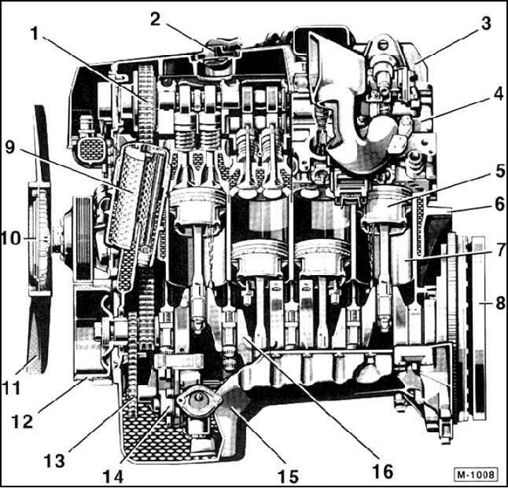
1. Double roller chain; 2. Oil filling cap; 3. Cylinder head cover; 4. Cylinder head; 5. Piston; 6. Flywheel; 7. Cylinder; 8. Flywheel 9. Oil filter; 10. Hydraulic clutch; 11. Fan; 12. Crankshaft pulley; 13. Oil pump drive chain; 14. Oil pump; 15. Oil pan; 16. Crankshaft
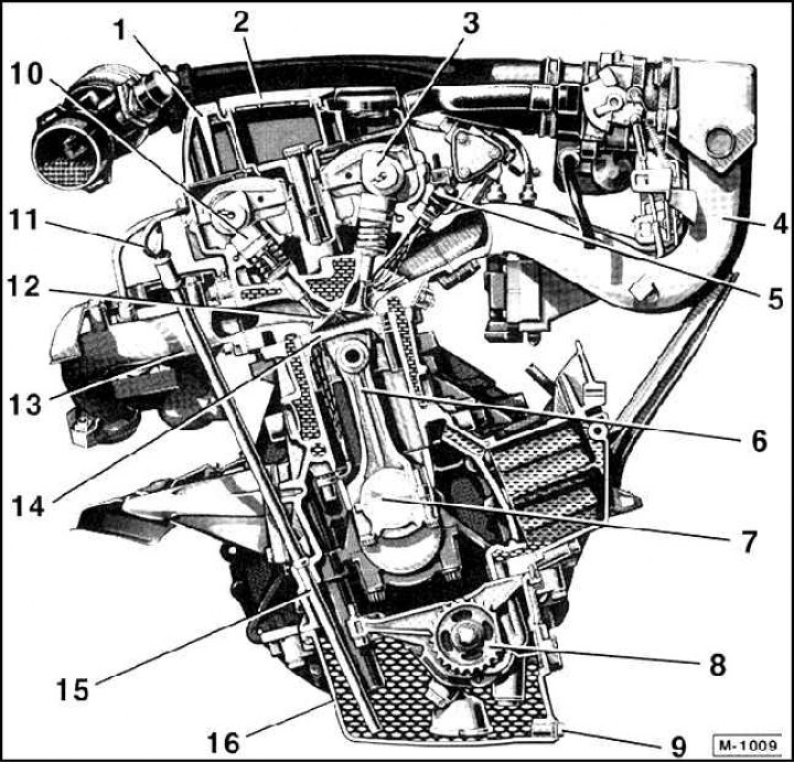
1. Cylinder head cover; 2. Ignition wire cover; 3. Intake camshaft; 4. Suction manifold; 5. Injection valve; 6. Connecting rod; 7. Crankshaft; 8. Oil pump; 9. Oil drain bolt 10. Hydraulic poppet; 11. Oil dipstick; 12. Exhaust valve; 13. Exhaust manifold; 14. Piston; 15. Oil dipstick guide tube; 16. Oil pan
In the Mercedes C-Class model, there are in-line, 4- or 6-cylinder engines.
The holes of the working cylinders are machined in the engine block from gray cast iron. If there are scores or scratches on their walls, they can be bored out in a specialized workshop. Therefore, the pistons must be installed in the working cylinders with an interference fit. At the bottom of the motor block is the crankshaft, which is fixed in 5 and 7 crankshaft bearings. The connecting rods that drive the pistons are connected to the crankshaft by means of a sleeve bearing. An oil pan is attached to the bottom of the engine - it collects engine oil required for lubrication and cooling. On top of the engine block is attached to the cylinder head, made of aluminum, which has good thermal conductivity and is much lighter than gray cast iron. The cylinder head is made on the principle of cross-flow. That is, the air-fuel mixture enters on one side of the cylinder head while the hot gases are pushed out the opposite side. Thanks to the cross-flow principle, better gas exchange is achieved. The cylinder head contains two camshafts, one for the intake and one for the exhaust valves. The four valves are directly driven from the camshaft via poppets. Hydraulic poppet tappets automatically maintain uniform valve clearance under all operating conditions, eliminating the need for valve clearance adjustment during maintenance.
The engine is lubricated by an oil pump. It is attached to the front of the cylinder block and is driven by an additional roller chain. The oil sucked in from the oil pan reaches the crankshaft and camshaft bearings, as well as the working surfaces of the cylinders, through holes and channels.
The coolant pump for 4-cylinder engines is attached to the front of the engine block, and for 6-cylinder engines it is mounted on the side of the engine block. The pump is driven by a ribbed V-belt, which additionally drives the alternator and steering pump. Please note that the cooling system circuit must be filled annually with a fresh mixture of antifreeze and anti-corrosion agent based on decalcified water.
A fully electronically controlled injection and ignition device is used to prepare the flammable air-fuel mixture, which requires almost no maintenance.
Engine model | ||||
C180 | C200 | C220 | C280 | |
| Start of release from | 6/93 | 1/94 | 6/93 | 6/93 |
| Type | 202.018 | 202.020 | 202.022 | 202.028 |
| Engine | 111.920 | 111.941 | 111.961 | 104.941 |
| Cylinder displacement, cm3 | 1799 | 1998 | 2199 | 2799 |
| Power, kW at rpm hp at rpm | 90/5500 122/5500 | 100/5500 135/5500 | 110/5500 150/5500 | 142/5000 193/5000 |
| Torque, N·m at rpm | 170/4200 | 190/4000 | 210/4000 | 270/3750 |
| Cylinder diameter, mm | 85,3 | 89,9 | 89,9 | 98,9 |
| Piston stroke, mm | 78,7 | 78,7 | 86,6 | 73,5 |
| Compression ratio | 9,8 | 9,6 | 9,8 | 9,8 |
| Number of cylinders | 4 | 4 | 4 | 6 |
| Injection / Ignition | PMS | PMS | HFM | HFM |
| The order of operation of the cylinders | 1–3–4–2 | 1–3–4–2 | 1–3–4–2 | 1–5–3–6–2–4 |
| Fuel / ROZ without lead | Super/95 | Super/95 | Super/95 | Super/95 |
| Filling capacities: | ||||
| - engine oil (with filter), l | 5,8 | 5,8 | 5,8 | 7,5 |
| – coolant, l | 8,0 | 8,0 | 8,0 | 10,0 |