



Since the piston rings cannot seal tightly enough, hot gases penetrate into the crankcase. The mixture of hot oil and fuel vapors can create excess pressure, which has a detrimental effect on the crank mechanism. To avoid this, the gases must be sucked out of the engine through a connecting hose and burned.
Closed ventilation of the engine does not require maintenance.
Engine ventilation ranges from "idle to partial load"
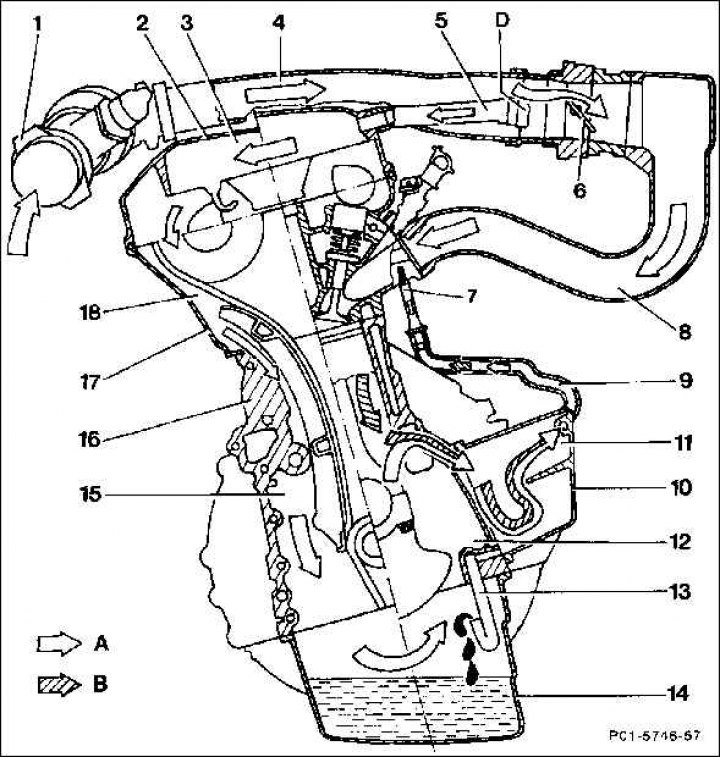
1. Hot film air mass meter; 2. Cylinder head cover; 3. Oil separator chamber; Ventilation top partial/full load; 4. Intake air line; 5. Exhaust air line; Ventilation top partial/full load; 6. Throttle valve; 7. Choke diameter 1.1 mm; 8. Suction tube; 9. Air bleed line 10. Power steering pump support; 11. Oil separator chamber; 12. Crank space; 13. Oil recirculation pipe (siphon); 14. Oil pan; 15. Control building; 16. Cylinder crank housing; 17. Cylinder head; 18. Chain housing; A. Fresh air; B. Blown gases; D. Connecting element
The mixture of ventilated gases is sucked into the combustion chamber from the crank chamber (12) through the oil separator chamber (11) and the air removal line, as well as the throttle (7) in the engine operating mode from "idle to medium partial load". In the oil separator, oil is separated from the gas mixture and enters through the outlet hole and the drain pipe (13) into the oil pan.
Article text obtained from the website: MercedesMAN.ru
To prevent slag from entering the engine oil, part of the sucked-in fresh air is separated in the connecting element (D) and directed to the crank chamber via the exhaust air line (5), the oil separator chamber (3), the chain housing (18) and the control housing (15).