
A defective gasket can be recognized by a number of signs.
Removing
1. Remove the air filter.
2. Drain the coolant, also from the crankshaft housing.
3. Disconnect the heating and coolant hoses from the cylinder head by first loosening the hose clamps.
4. Disconnect the battery ground wire (–).
Attention! This erases the anti-theft code of the radio. See the instructions under the battery removal subsection.
5. Set the first cylinder of the engine to TDC. To do this, move the transmission to idle and apply the parking brake. Turn the crankshaft until the markings match with a wrench with an SW27 nozzle on the central bolt of the crankshaft belt pulley in the direction of engine rotation, i.e. clockwise.
6. Pull out the retaining tab on the fan shroud ring. Rotate the casing in the direction of the arrow "open" and extract.
7. Remove the cylinder head cover.
8. Remove the chain tensioner.
Attention! The chain tensioner must be removed, because when the top bar is removed, it automatically pulls the ratchet. This can lead to excessive chain tension.
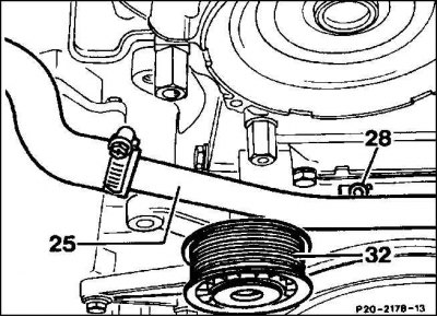
9. Unscrew the hot fluid recirculation line (25) from the locking cover (28), if available.
10. Disconnect the plug connections of the camshaft position sensor.
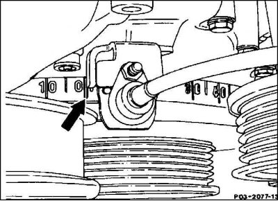
11. Unscrew the shock absorber tensioner pulley from the front cover, push down and turn. Keep an eye on the adjacent washer, be sure to install it during subsequent assembly.
12. Remove the bolts (arrow) front cover. Remove the bolt cover (With).
13. unscrew the bolts (d) coolant recirculator, if equipped.
14. Mark the position of the camshaft gears in relation to the control chain with a felt-tip pen or paint.
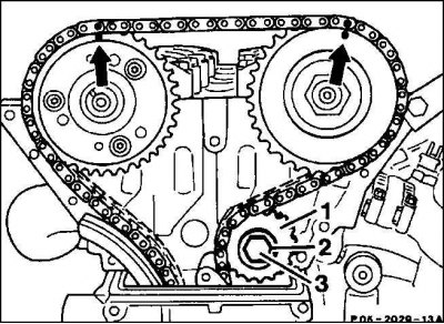
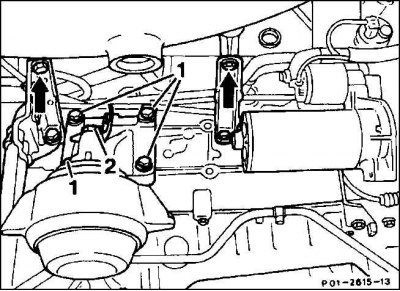
15. Loosen the bolts (3) bypass wheel (1), if available.
Attention! The bolt has a left-hand thread, twists to the right.
16. Remove the parts together with the support (2).
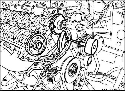
17. Pull out the guide bar pins with a puller or other suitable tool.
18. Unscrew the anchor of the camshaft adjuster.
19. Dismantle the set of wires going to the engine, namely, loosen all wire connectors and remove them together with plug connections.
20. Disconnect the tempomat mechanism, if present.
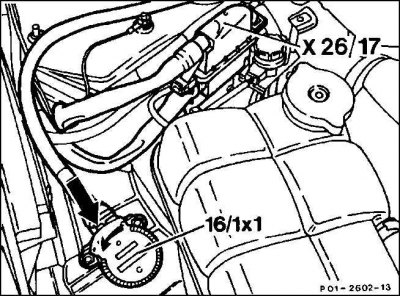
21. Disconnect the plug connection at the connector (Х26/17). Disconnect the electronic accelerator pedal actuator connector (16/1х1), for which press the locking latch (arrow). In this case, the plug is rotated by 90°by means of a helical spring. Remove the motor wire set from the conduit.
22. Unscrew the front exhaust pipe from the exhaust manifold.
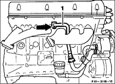
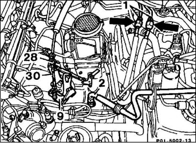
23. Unscrew the air suction hose (1) on the cylinder head.
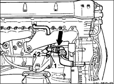
24. Disconnect the hose from the air intake check valve (arrow), unscrew the holder.
25. Unscrew the oil level gauge guide tube holder and intake pipe support (arrows).
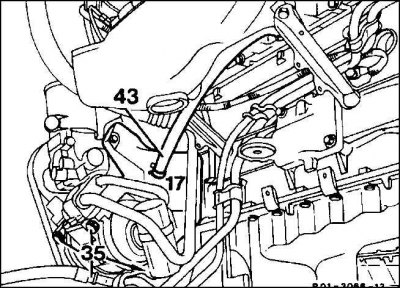
26. Disconnect the ventilation hose (43) crankcase from the combined support (17).
27. Briefly open the fuel tank cap to relieve excess pressure. Then unscrew the fuel lines (arrows).
28. Unscrew vacuum hose (2) from the intake pipe.
29. Disconnect the throttle cable (30) from the throttle valve.
30. For automatic transmission: unscrew the guide tube of the oil dipstick from the cylinder head.
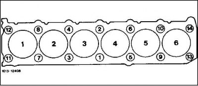
31. Unscrew the cylinder head bolts with a socket wrench, for example, HAZET 990SLg-12, in the reverse order of the numbering in the figure, i.e. from 14 to 1. Cylinder 1 is located in the engine ventilation side.
32. Raise the cylinder head with a repair crane. To do this, thread a suitable cable or rope through the eyes.
Installation
1. Before installing the cylinder head and cylinder block, clean the sealing surfaces of sealant residues with a suitable scraper. Make sure no sealant remains in the holes. Cover the holes with a rag.
2. Check the flatness of the cylinder head and engine block in the longitudinal and transverse direction with a steel ruler, modify if necessary (work for repair shops).
3. Check the cylinder head for scratches and the cylinder running surface for scoring.
4. Thoroughly clean the cylinder head bolt holes of oil and other deposits.
5. Be sure to replace the cylinder head gasket.
6. Apply a new gasket without sealant so that the holes are not blocked.
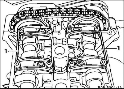
7. Before installing the cylinder head, check that the camshafts are at TDC. Pins can be installed in this position (1) 4 mm diameter directly above the upper edge of the cylinder head into the flanges of the camshaft gears. The crankshaft must also be at TDC.
8. Install the cylinder head.
Attention! The cylinder head is fixed with dowel pins in the cylinder block.
9. Measure the length of the cylinder head bolts from the bottom edge of the bolt head, which is 160mm long when reinstalled. For a length of 162.7 mm, replace the bolts.
10. Lubricate the cylinder head threads and bolt heads. Install the bolts and tighten them by hand.
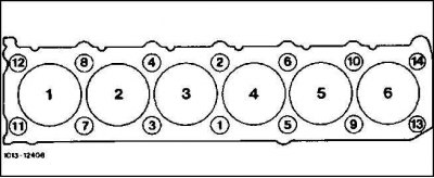
11. Tighten the cylinder head bolts in sequence from 1st to 14th in three steps. First tighten the bolts with a torque wrench to 55 Nm. In the second step, tighten all bolts 1 to 10 by 90°with an open end wrench. On the third - further tighten the bolts 1 to 10 by another 90°with an open-end wrench.
Attention! Carefully tighten the cylinder head bolts. Before tightening, check the accuracy of the torque wrench.
Attention! When tightening the bolts for estimating the angle of rotation, position the wrench handle along the engine and turn in one motion until the handle is across the engine.
12. Apply the control chain to the camshaft gears, observing the markings made during disassembly.
13. Remove the 4 mm pins from the camshaft flanges.
14. Connect the coolant hose to the coolant pump and secure with hose tape.
15. Attach the throttle cable and adjust it.
16. Connect the tempomat mechanism, if available.
17. Automatic transmission: screw the guide tube of the oil level gauge on the back of the cylinder head.
18. Screw the return and direct fuel pipes together, do not pinch their connection points.
19. Screw the vacuum line for the brake booster to the intake pipe. Push the crankcase breather hose onto the combination support and secure with a hose clamp.
20. Screw on the oil level gauge guide tube holder and intake pipe support.
21. Install the air intake pipe with connecting hose to the cylinder head. Use a new O-ring between the pipeline and the cylinder head.
22. Attach the electrical plug for the motor wiring kit and route it in the cable duct. Install the wire connector.
23. Screw the armature to the camshaft adjuster.
24. Screw with a torque of 35 Nm the chain take-off gear with support, if equipped (left hand thread).
25. Insert the guide rail pins into the motor block.
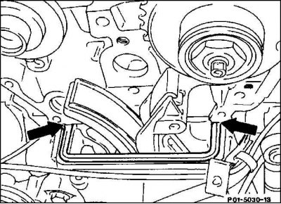
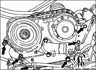
26. For sealing into the grease-free groove of the cover of the control housing on the left and right at the joint (arrow) on the cylinder head, apply sealant, Mercedes-N001 9896120, according to the points. Other sealants, such as Omnifit FD 10 or Curil, can also be used instead.
27. Insert a new seal without sealant into the grease-free groove. Cover the front cover in the places where it fits to the cylinder head with sealant 002 989 00 20 10.
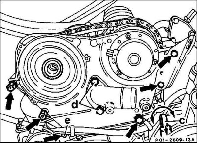
28. Install the front cover with the bottom bolt inserted (e). Tighten the lower bolts first with a torque of 20 Nm.
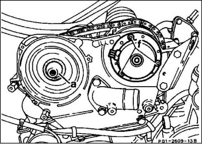
29. Screw the camshaft adjuster, the thread of the mounting bolts (f) seal with sealant such as Curil.
30. Lubricate the radial sealing ring with engine oil and put it on the camshaft. To prevent the sealing ring from being damaged along the edge, pre-paste the camshaft connection elements with tape, remove the tape after installing the sealing ring. Specialist workshops instead have an inlet sleeve with a diameter of 20 mm.
31. Screw the shock absorber tensioner with gasket on top.
32. Screw on the coolant recirculator, if equipped.
33. Attach the electrical plugs to the position sensor and camshaft adjuster.
34. Install the chain tensioner.
35. Install the fan shroud ring, turn and lock.
36. Install the cylinder head cover.
37. Connect the plugs of the spark plugs to the ignition coils.
38. Install the air filter.
39. Screw the exhaust pipe to the manifold.
40. Connect the coolant hoses to the cylinder head and secure with clamps.
41. Fill with coolant.
42. Connect the battery.
43. Set the time on the clock.
44. Set the radio's anti-theft code.
45. Warm up the engine to its operating temperature and check all connections for leaks.