



Contents: Removal ↡ Installation ↡
Cylinder head bolts
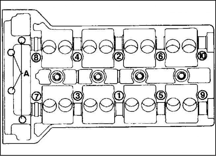
Remove the cylinder head only when the engine is cold. The exhaust and intake manifolds remain connected.
A defective cylinder head gasket can be identified by the following signs:
- loss of power;
- coolant leak, white exhaust gas when engine is warm;
- oil leak;
- coolant in engine oil, oil level does not fall, but increases;
- gray color of engine oil, wisps of foam on the dipstick, oil is thin;
- engine oil in coolant;
- the coolant is bubbling violently;
- there is no compression in two adjacent cylinders.
Removal
1. Lift the engine hood.
2. Disconnect the battery ground (–) cable.
Warning! Disconnecting the battery will erase the radio's anti-theft code. For instructions, see subsection 13.1.7.
3. Remove the cylinder head housing.
4. Remove the coolant thermostat.

5. Remove the two 8mm diameter bolts (1) on both sides of the front cover (23). There are relief bushings at the rear of the cover.
6. Remove the bolts (2) (thread diameter 6 mm).
7. Remove the cover (23), paying attention to the O-ring between the cover and the cylinder head. Clean the sealing surfaces.
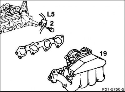
8. Unscrew the intake manifold (19) from the cylinder head and set it aside with the wires connected.
9. Unscrew the holder (2) of the crankshaft position sensor located at the rear of the cylinder head.
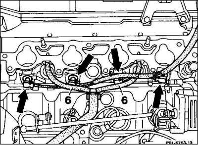
10. Disconnect the ventilation hoses (6) at the bottom of the cylinder head.
11. Disconnect the lambda probe connection plug (in the battery area).
12. Unscrew the dipstick guide tube in the cylinder head. For automatic transmission, also unscrew the dipstick guide tube behind the cylinder head.
13. Drain the coolant, including from the crankcase.
14. Unscrew the exhaust pipe from the exhaust manifold.
15. 2.2L engine: Turn the camshaft adjuster all the way to the right in the "spat" (late) direction.
16. Set the engine to 20° after TDC of the first cylinder and remove the chain tensioner.
17. Mark the position of the timing chain in relation to both camshaft gears with paint by drawing a line through the chain and sprocket.
18. Unscrew the exhaust camshaft pulley from the crankshaft flange.
19. 2.0L engine: Remove the intake camshaft gear.
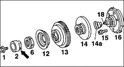
20. 2.2L engine: Hold the camshaft adjuster anchor (2) and unscrew the flange bolt (1). Remove the anchor from the control piston (18). Unscrew the nut (6).
21. Remove the control chain.
22. 2.2L Engine: Mark the position of the intake camshaft gear in relation to the flange shaft by drawing a paint line across both parts. Remove the cover (12), intake camshaft gear (13), adjusting piston (14) and spherical spring (14a). Remove the flange shaft (16).
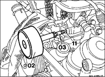
23. Pull out the guide pins (11) using an impact puller or suitable tool.
24. Remove the four combination bolts (A) between the upper and lower chain case covers. Remove the cylinder head bolts in the reverse order of their numbering in the figure, i.e. from tenth to first. For this, you will need a socket wrench attachment, such as HAZET 990 SLg-12 (see fig. Cylinder head bolts).
25. Raise the cylinder head. This can also be done with a crane, threading the appropriate cable or chain through the eyes.
Installation
1. Before assembly, clean the cylinder head and cylinder block from sealant residues using a suitable scraper. Make sure that these residues do not get into the holes. To do this, cover the holes with a rag.
2. Using a steel ruler, check the cylinder head and engine block for flatness in the longitudinal and transverse directions; if necessary, modify them (in the repair shop).
3. Check the cylinder head for cracks and the working surface of the cylinder for marks and scratches.
4. Clean the cylinder head bolt holes from oil and other deposits.
5. Be sure to replace the cylinder head gasket.
6. Apply a new gasket without sealant so that the holes are not covered.
7. Install the cylinder head. Before installing, make sure that the camshafts and crankshaft are in the same position as when removed and are not rotated.
Attention! The cylinder head is centered in the cylinder block by means of dowel pins.
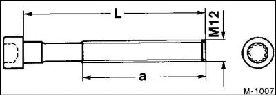
8. Measure the length of the cylinder head bolts, which when new is 102 mm. Keep to this length when tightening. If the length is 105 mm, replace the cylinder head bolts.
9. Lubricate the threads of the cylinder head bolts and the area where they fit onto the cylinder head with oil, install the bolts and tighten by hand.
10. Tighten the cylinder head bolts in sequence from 1 to 10 (see fig. Cylinder head bolts) in three stages.
Caution! Tighten the cylinder head bolts carefully. Check the torque wrench for accuracy before tightening.
First tighten the cylinder head bolts 1 through 10 in sequence with a torque wrench to 55 N·m. In the second step, tighten all bolts 1 through 10 an additional 90° with an open-end wrench. In the third step, tighten the cylinder head bolts 1 through 10 an additional 90° in the same direction with an open-end wrench.
Caution: When tightening the cylinder head bolts, position the wrench handle lengthwise along the engine and turn it in one motion until it is positioned across - for a 90° turn.
11. Tighten the control housing cover combination bolts (A) to 20 Nm.
12. Coat the guide pins with Mercedes N 002 989 00 20 10 sealant or other suitable sealant and drive in.