
The replacement of oil seals for a 4-cylinder engine is described below, and for a 6-cylinder engine, proceed according to the meaning, using the appropriate tool.
Removing
Attention! If the valve control parts are to be used again, they must be mounted in the same places. In order not to confuse the parts, make a special panel for storing them.
1. Remove camshafts.
2. Remove the spark plugs.
3. Remove the protective cover of the engine wires on the front wall of the body.
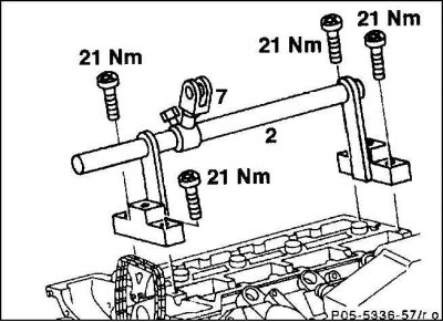
4. Screw on the jumper (2) with moving part (7) to bearings 1 and 5 of the camshaft or later to bearings 6 and 10 with a torque of 20 Nm.
5. Turn the corresponding cylinder piston to TDC with a socket wrench. 4-cylinder engine: at TDC position of the pulley, pistons 1 and 4 are at TDC. When the 180-degree mark of the belt pulley coincides with the base mark, the pistons of cylinders 1 and 6 are at TDC. 6-cylinder engine: at the TDC position of the belt pulley, the pistons of cylinders 1 and 6 are at TDC. cylinders 2 and 5; at a 240-degree mark - the pistons of cylinders 3 and 4.
Attention! When turning the crankshaft, raise the control chain high so that it does not jam.
6. Hang the lever pusher.
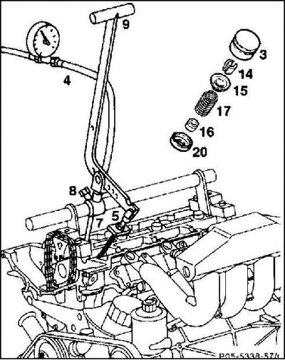
7. Pull out poppet (3) rubber suction cup (diameter 30 mm), for example, HAZET 735-2.
Attention! Do not use a magnetic siphon for this, as the sliding surface of the poppet follower is magnetized, and subsequently the smallest metal chips are deposited on it, which leads to damage to the pusher and cams.
8. Lock the crankshaft. To do this, set the first gear and tighten the parking brake.
9. Install an overpressure of at least 6 bar in the combustion chamber of the cylinder. To do this, screw in the connecting hose (4) cylinder leak tester into the spark plug hole. If a leak tester is not available, a matching hose can be made using an old spark plug.
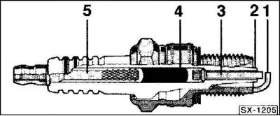
10. Bite off the electrode "masses" old spark plug (1). Break off ceramic insulator (2) with a screwdriver, and also break off, swinging back and forth, the middle electrode (3) and extract. Push out punch (about 3 mm) remnants of the middle electrode with glass melt (4) and connecting pin (5). When doing this, clamp the spark plug in a vise or use an appropriate screw-cutting machine.
Attention! Be careful not to damage the threads of the spark plug, so as not to spoil the threads of the hole in the cylinder head.
11. Screw the spark plug into the appropriate cylinder, connect it to the air pressure hose and pressurize the cylinder to at least 6 bar.
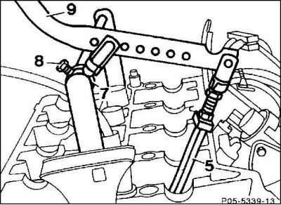
12. Install lever pusher (9) with pressure detail (5) on the valve spring seat. Position the pressure piece and the moving piece parallel to each other. Secure the moving part with a bolt (8).
13. Compress the valve spring.
Attention! Do not compress the valve spring without compressed air, otherwise the valves and pistons may be damaged.
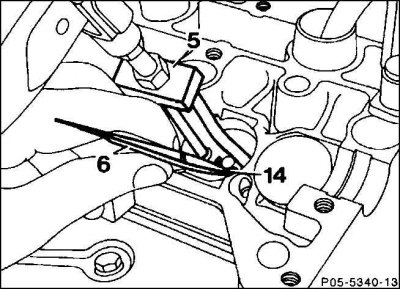
14. Valve stem parts (14) remove from valve stem with tweezers (6) or magnetic siphon.
15. Remove the valve spring cap (15) and valve spring (17).
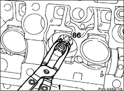
16. Remove the oil seal (86) from the valve stem with special pliers, eg HAZET 791-6.
Attention! Be careful not to damage the valve stem and guide.
17. Remove the valve spring cap (15) and valve spring (17).
18. If necessary, deburr the valve stem groove with a fine emery cloth.
19. Check the wear of the valve guides in the area of their contact with the valve stem seals. Replace valve guides (work for repair shops).
Installation
1. Replace bent parts of the stem, valves and spring plate.
2. Valve guides that deviate from the slinger cap retaining groove must be replaced (workshop work).
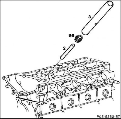
3. Put on the protective sleeve (2) on the valve stem.
4. Lubricate the oil seal with oil (86) and fit manually using the mounting mandrel.
Attention! The mounting mandrel is included in the repair kit. When fitting without a mounting mandrel, the sealing chamfer of the flinger cap is damaged.
5. Install and secure the valve springs and valve spring plate.
6. Insert the parts of the valve stem, decompress the valve springs.
7. Install the poppet pusher.
8. Replace the oil seal.
9. Unscrew the spark plugs.
10. Install the camshafts.
11. Attach the cover of the engine wiring kit to the front wall of the body.