
Note. The camshafts can be turned without the risk of the valves colliding with the pistons when the crankshaft is brought to a position of 30°before TDC of the first cylinder.
Note. The timing chain can be replaced without dismantling the engine. Using the tools listed below, the new chain can be connected to the old chain, passed around the sprockets and minted.
Attention! If assembled incorrectly, the valves may collide with the piston crowns!
General information
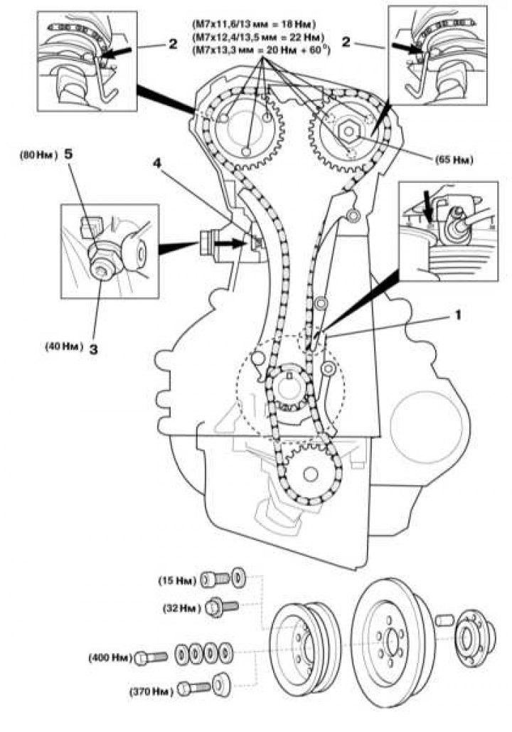
Installation details of timing drive elements (the gas distribution chain consists of 126 links)
1 - Setting marks for bringing the engine to the TDC position of the end of the compression stroke of the first cylinder; 2 - Rods with a diameter of 4 mm for fixing the camshafts; 3 - When installing the chain, make sure that the lugs of the camshaft adjuster [3] are in position «delays».; 4 - Spring-loaded tensioner nut; 5 - Pin; 6 - Spring; 7 - Plunger; 8 - Tensioner body
The following special tools are required to perform the removal and installation procedures for the timing drive components:
- Camshaft Key (type 1) - № 104589010100;
- Camshaft Key (type 2) - № 119589000100;
- Crankshaft hub / pulley puller - No. 103589003300;
- Crankshaft sprocket puller - No. 615589013300;
- Flywheel/drive plate locking tool - No. 601589024000;
- M6-90 bolts for fixing the flywheel/drive plate locking tool;
- Tool for installing gas distribution chain links - No. 602589003900;
- A set of stamp holders for installing gas distribution chain links - No. 112589096300;
- Timing chain link puller (element 1) - № 602589023300;
- Timing chain link puller (element 2) - № 602589056300;
- Viscous clutch puller holder (series 129/140) - № 120589020100.
Pay attention to the following points:
- Unless otherwise stated, turn the engine in the normal direction only;
- Observe the tightening torques of the fasteners stipulated by the regulations;
- With the appropriate configuration, do not forget to mark the installation position of the CKP sensor before removing it;
- Do not turn the crankshaft using the camshaft sprockets, as well as other timing sprockets;
- Do not turn the crankshaft and camshafts with the timing chain removed.
Servicing Timing Drive Components
1. Disconnect the negative cable from the battery.
2. For the purpose of simplification of cranking of the engine turn out all spark plugs.
3. Insert the locking rods into the camshafts (2) 4 mm in diameter.
4. When installing the chain, make sure that the camshaft adjuster lugs (3) were in position «delays».
Attention! If assembled incorrectly, the valves may collide with the piston crowns! 5. Before repairing the engine, loosen the tensioner nut one turn.
6. Remove tensioner assembly.
7. Fully release the spring-loaded nut (4) tensioner.
8. Remove pin (5) and remove the spring (6).
9. Push plunger (7) into the tensioner (8) in the direction indicated by the arrow.
10. Install tensioner housing (8) and tighten it to 80 Nm.
11. Prime plunger (7), install the spring (6) and pin (5).
12. Screw the tensioner nut (4) and tighten it to 40 Nm.
13. Tighten the new intake camshaft adjuster bolt to 7 Nm (type A bolt with separate washer) or 5 Nm + 90° (type B bolt with built-in washer).
Attention! The M7x13.3 mm bolts for the intake and exhaust camshaft sprocket are disposable and must be replaced without fail!
Note. During repair work, the type A bolt should be replaced with a disposable type B bolt.
14. Do not forget to lubricate the central bolt of the crankshaft pulley and its washer before installation (s).