
Note. See also Section Timing drive - general information, component maintenance.
Removing
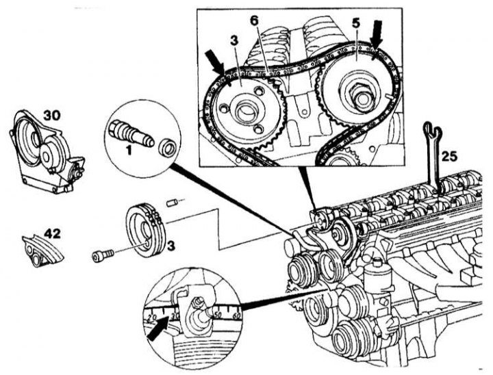
Removing camshafts
1 - Timing chain tensioner; 3, 5 - Camshaft sprockets; 6 - Timing chain; 25 - Key; 30 - Front cover; 42 - Upper guide arm
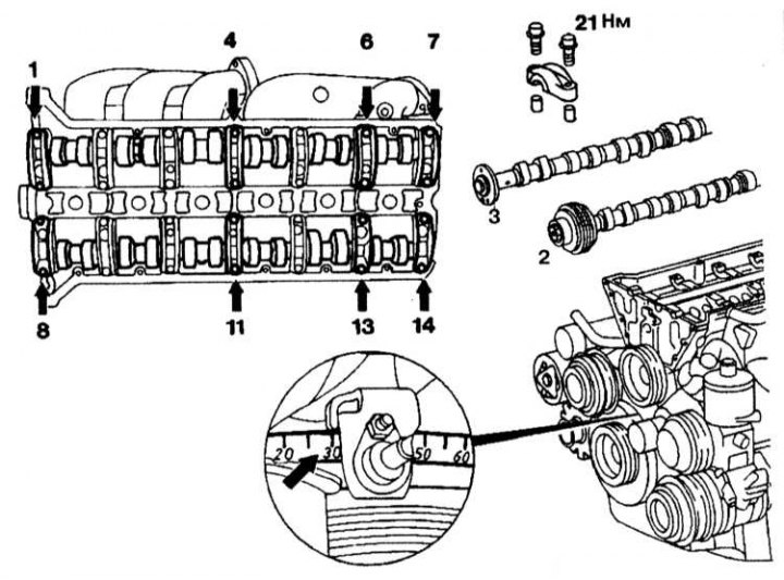
Removing camshafts
1, 4, 6, 7, 8, 11, 13, 14 - Camshaft bearing caps
2 - Intake camshaft
3 — Final camshaft
1. Set the piston of the first cylinder to the position 30°before TDC.
2. Remove the chain tensioner.
3. Remove the front cover (30) and upper guide arm (42).
4. Mark the position of the camshaft sprockets in relation to the timing chain (6) (arrow).
5. Unscrew the sprocket (3) exhaust camshaft.
6. Remove the timing chain (6) from stars (5) intake camshaft.
7. Turn the camshafts with a wrench so that the cams of the camshafts of the second cylinder set the hydraulic compensator to the middle position.
8. Turn away bolts of fastening of covers of bearings (1), (4), (6) And (7) graduation and (8), (11), (13) And (14) intake camshafts. The camshafts cannot be turned while loosening or loosening the bearing cap bolts.
9. Turn away bolts of fastening of other covers, and remove camshafts.
Installation
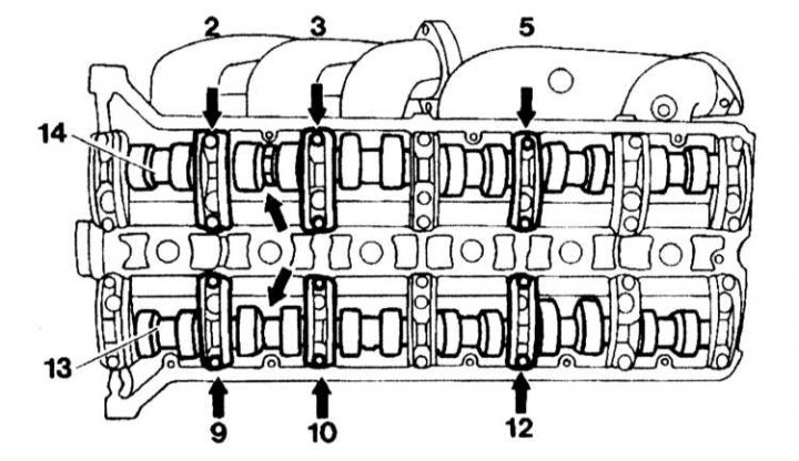
Installation of camshafts
2, 3, 5, 9, 10, 12 - Bearing caps
13, 14 - Camshafts
1. Check hydraulic lifters.
2. Lubricate all hydraulic lifters and bearing caps.
3. Install the camshafts in the bearing bed with the piston of the first cylinder in position 30°before TDC.
4. Install covers (2), (3) And (5) graduation and (9), (10) And (12) intake camshafts.
5. Tighten the camshaft bearing cap bolts to 21 Nm.
6. Install the remaining bearing caps and tighten the mounting bolts.
7. Establish an asterisk of a final camshaft and wrap bolts of fastening.
8. Install the chain on the camshaft sprockets according to the previously made marks.
9. Install front cover and upper guide arm, timing chain tensioner.
10. Check up a control position of camshafts.
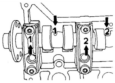
11. The camshafts have a code designation on the third neck (arrows) (behind the bearing cap) or paint on the camshaft flange.
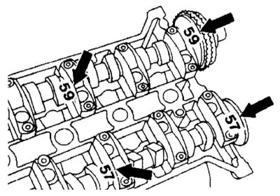
12. Bearing caps are marked. The numbering of the bearing caps is molded into the cylinder head. Bearing caps must be installed according to the numerical code. The intake camshaft can be removed or installed with the sprocket.
13. The repair dimensions of the camshaft bearings are given in Specifications.