



Removal
1. Remove the sliding lever 3 (see figure 2.24).
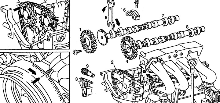
Figure 2.24. Camshafts:
1. Exhaust camshaft pulley,
2. Drive chain,
3. Sliding lever,
4. Intake camshaft pulley,
5. Key, 6. Bearing cover,
7. Exhaust camshaft,
8. Intake camshaft,
9. Chain tensioner.
2. Set the piston of the first cylinder to the position 30° after TDC.
3. Mark the position of camshaft pulleys 1 and 4 relative to drive chain 2.
4. Remove chain tensioner 9.
5. Remove the exhaust camshaft pulley 1.
6. Remove drive chain 2 from intake camshaft pulley 4.
7. Using key 5, turn camshafts 7 and 8 so that the cams are free.
8. Remove the camshaft bearing caps (see figure 2.25).
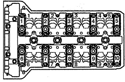
Figure 2.25. Marking of camshaft bearing caps.
9. Remove camshafts 7 and 8.
Installation
10. Installation is carried out in the reverse order of removal. Lubricate hydraulic lifters and camshaft bearings. Install camshafts 7 and 8 in the bearings so that the main circle of the cam rests on the hydraulic compensator. Replace the camshaft pulley mounting bolts and install exhaust camshaft pulley 1 with chain 2 fitted. Install drive chain 2 according to the marks made before removal. Check and adjust the basic position of the camshafts.
Examination
11. Remove the cylinder head cover 1 (see figure 2.26).
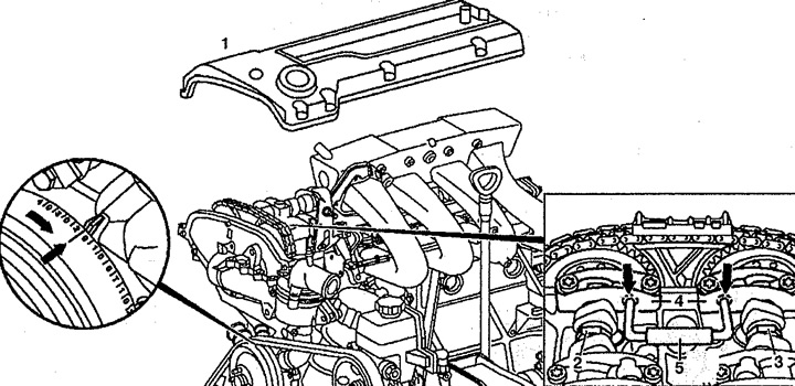
Figure 2.26. Checking the basic position of the camshafts:
1. Cylinder head cover,
2. Intake camshaft,
3. Exhaust camshaft,
4. Camshaft bearing cap,
5. Locking pin.
12. Set the piston of the first cylinder to the position 20° after TDC (the 20° mark is marked on the crankshaft groove pulley). Cams 2 and 3 of the valves of the first cylinder should be directed upwards.
13. Check the basic position of the camshafts. To do this, insert locking pin 5 into the holes of the bearing cap 4 of the camshafts (arrow).
14. If the locking pin does not fit into both holes, adjustment must be made.
Adjustment
5. Remove the sliding lever from the cylinder head.
6. Set the piston of the first cylinder to the position 30° after TDC.
7. Remove the chain tensioner 1 (see figure 2.27).
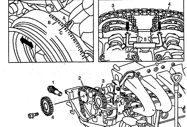
Figure 2.27. Adjusting the position of the camshafts:
1. Chain tensioner,
2. Drive chain,
3. Intake camshaft,
4. Exhaust camshaft,
5. Camshaft bearing cover,
6. Locking pin.
A. Mark on the chain drive cover,
B. Basic position of the crankshaft for adjusting the position of the camshafts,
C. Crankshaft position to check camshaft position.
8. Remove the exhaust camshaft pulley 4.
9. Remove chain 2 from intake camshaft pulley 3.
10. Rotate the camshafts until they are set to the main position and locked with locking pin 5.
11. Set the piston of the first cylinder to the position 20° after TDC.
12. Install chain 2 on intake camshaft pulley 3.
13. Install the exhaust camshaft pulley 4 with the chain 2 placed on it. Replace the camshaft pulley mounting bolts.
14. Install the chain tensioner
15. Remove locking pin 5.
16. Check the basic position of the camshafts. To check, rotate the crankshaft twice in the direction of rotation.
[Material taken from a web resource www.mercedesman.ru]
17. Install the sliding lever into the cylinder head.