
Removing
1. Disconnect the negative cable from the battery.
2. Remove the generator and secure it to the side without disconnecting the wiring.
3. Remove tensioner 13 assembly (see fig. 2.10). The tensioner assembly is shown in fig. 2.10.
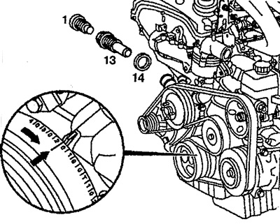
Pic. 2.10. Chain tensioner:
1. Thrust piece,
13. Tensioner,
14. Limiter.
Installation
4. Install tensioner 13, alternator, connect negative wire to battery.
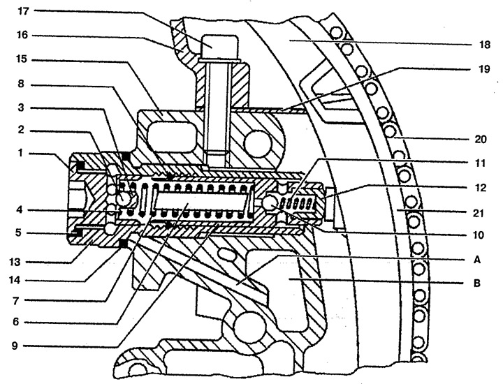
Pic. 2.11. Sectional view of chain drive tensioner:
1. Thrust piece,
2. Ball check valve,
3. Ball guide,
4, 7, 11. Pressure spring,
5, 14. Limiter,
6. Finger,
8. Spring lock,
9, 17. Bolt,
10. Control valve ball,
12. Glass,
13. Tensioner housing,
15. Chain drive cover,
16. Cylinder head,
18. Tension lever,
19. Cylinder head gasket,
20. Chain,
21. Plastic part of the tension lever.
A. Oil line for tensioner lubrication,
B. Oil pan for tensioner.