
Removing
1. Warm up the engine to an operating temperature of 80°C. Check the engine oil level and correct it.
2. Remove the cylinder head cover 1 and, rotating the crankshaft, set the cam 2 of the checked hydraulic compensator 3 up (see fig. 2.34).
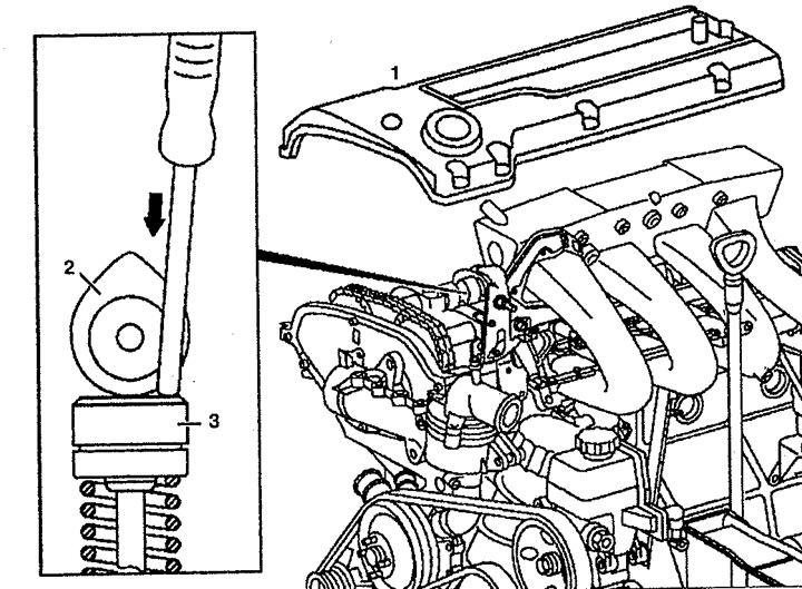
Pic. 2.34. Remove the cylinder head cover 1 and set the cam 2 of the checked hydraulic compensator 3 up:
1. Cylinder head,
2. Cam,
3. Hydraulic compensator.
3. Wipe the hydraulic lifters 3 with a clean cloth. They must be oil free.
4. Remove the hydraulic compensator 3 using a manual vacuum pump
4. Do not use a magnet to remove (see fig. 2.35).
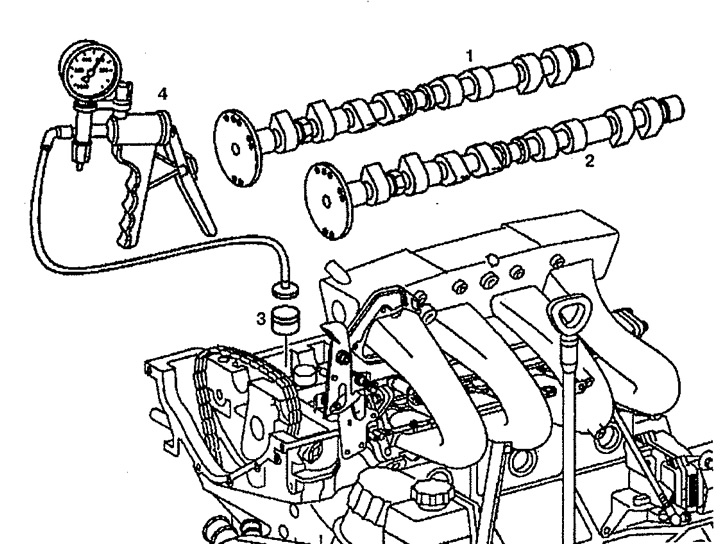
Pic. 2.35. Removing the hydraulic lifter using a manual vacuum pump:
1. Exhaust camshaft,
2. Intake camshaft,
3. Hydraulic compensator,
4. Manual vacuum pump.
Examination
5. Press the hydraulic compensator with a metal rod with your hand (arrow). If the pressure is excessive, the hydraulic compensator will lower and the valve will open. If the hydraulic lifter drops quickly compared to others, it must be replaced.
6. Press once on the hydraulic compensator by hand using the rod (arrow). If one or more of the new hydraulic lifters drop more than the others, check the oil supply for leaks. Clean the oil passages in the cylinder head if necessary.
Installation
7. Installation is made in an order, the return to removal. The design of the hydraulic compensator is shown in fig. 2.36.
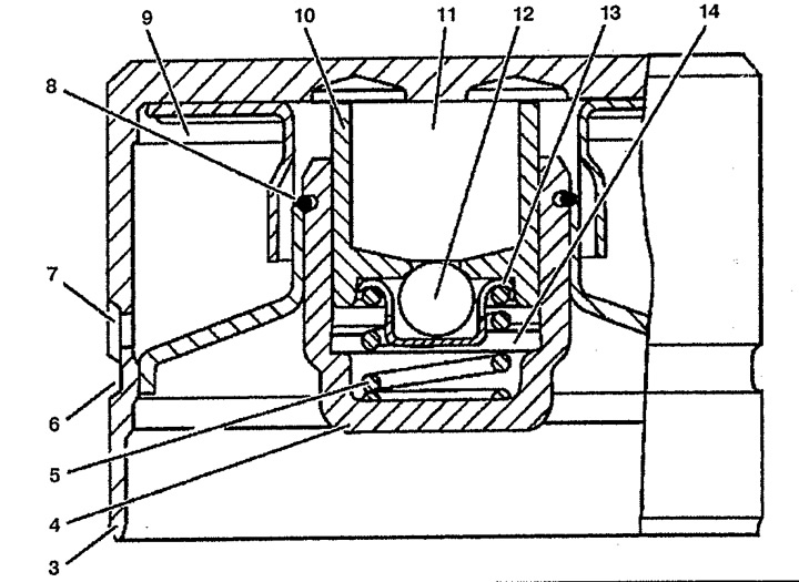
Pic. 2.36. Hydraulic compensator design:
3. Hydraulic compensator,
4. guide cup,
5. Spring,
6. Lubrication channel,
7. Oil hole,
8. Blocking ring,
9, 11. Oil chamber,
10. Bolt,
12. Ball,
13. Ball guide,
14. Working chamber.