
Removing
1. Insert adapter 1 into the spark plug hole and apply air pressure to the combustion chamber (minimum 5 bar), only if the cylinder head is mounted on the cylinder block (see fig. 2.37).
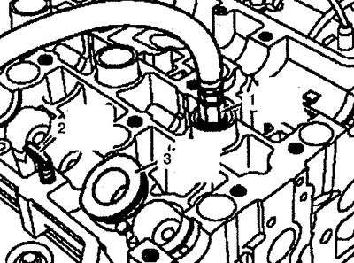
Pic. 2.37. Insert adapter 1 into the spark plug hole and apply air pressure to the combustion chamber (minimum 5 bar).
2. Install the guide sleeve 3 in the cylinder head, screw the fixing tool 2 into the cylinder head.
3. Install guide 5 (see fig. 2.38).
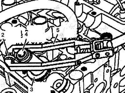
Pic. 2.38. Install guide 5.
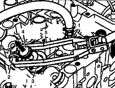
4. Place the chuck 4 in the guide bush 3, attach the guide 5 to the mounting tool 2 and lightly tighten it over the two chuck bolts 4. Using light pressure on the guide, slowly turn the knurled bolt on the chuck to the right (arrow) until the felt is seated correctly in the slot between the valve grommets.
5. Push guide 5 down until it comes to a complete stop (arrow) (see fig. 2.39). After that, press with your finger on the knurled bolt of cartridge 4 (arrow). Guide 5 must be installed vertically (if possible) on chuck 4 to prevent jamming of chuck 4.
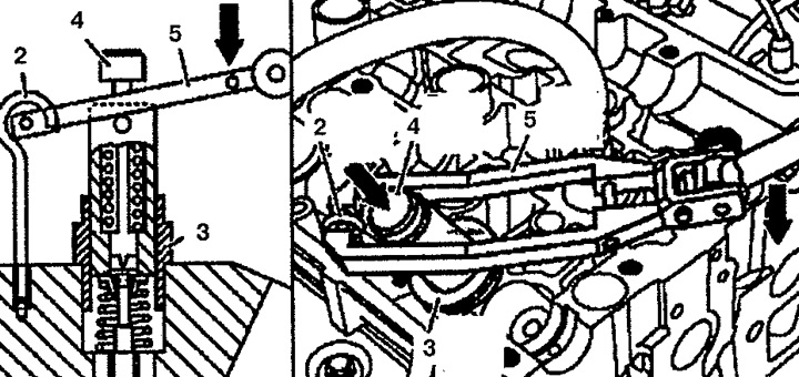
Pic. 2.39. Push guide 5 down until it comes to a complete stop (arrow).
6. Loosen the chuck 4 and guide 5 and remove them. Valve cotters are removed automatically.
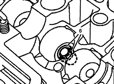
7. Check the presence of crackers 6 in cartridge 4, repeat, if necessary, operations 4 to 6 (see fig. 2.40).
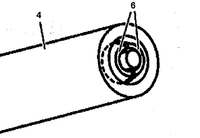
Pic. 2.40. Check the presence of crackers in the cartridge.
8. Remove guide sleeve 3, spring retainer 7 and spring 8 (see fig. 2.41).
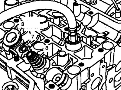
Pic. 2.41. Remove guide sleeve 3, spring retainer 7 and spring 8.
9. Remove valve stem seal 1 using pliers 9 (see fig. 2.42).
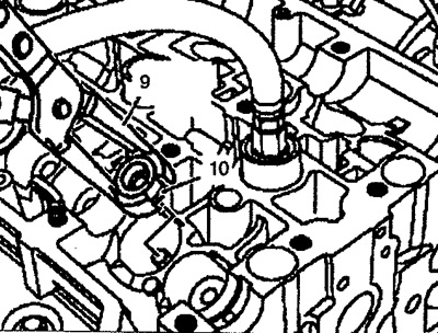
Pic. 2.42. Remove the valve stem seal with pliers.
10. Remove the spring plate, check for damage and, if necessary, replace it and install a new one.
11. Install the protective cover 11 on the valve stem (see fig. 2.43).
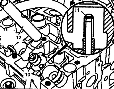
Pic. 2.43. Install the protective cover on the valve stem.
12. Install a new retainer 10 on the valve stem and press it in using tool 12.
13. Remove protective cover 11.
14. Install spring 8 and spring retainer 7 (see fig. 2.44).
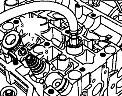
Pic. 2.44. Install the spring and spring retainer.
15. Install the guide sleeve 3 in the cylinder head (see fig. 2.45).
Pic. 2.45. Installation of valve cotters.
16. Install the cartridge 4 with valve cotters and insert them into the guide sleeve 3, attaching the lever 5 to the fixing tool 2 and lightly tighten it on the two cartridge bolts 4. Push the guide device 5 down to a complete stop (arrow). After that, remove the knurled bolt from the chuck 4 (arrow) and after a while loosen the guide 5 (see fig. 2.45). Rusks are installed automatically.
17. Remove all accessories from the cylinder head, except for the adapter with connector 1.
18. Check the correct installation of crackers 6. Remove the air supply hose from the cylinder head with an adapter (see fig.2.46).
Pic. 2.46. Checking the installation of valve cotters.