



Removal
1. Remove the pistons.
Examination
2. Check the connecting rods for blue color, scoring and recesses (notches). A connecting rod with blue color, scoring and recesses (notches) must be replaced. Replace the connecting rod and compensate for its difference in mass using balancing weights (see table 2.3).
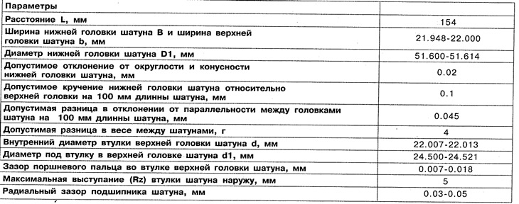
Table 2.3. Connecting rod dimensions
3. Check the connecting rod cap mounting bolts.
4. Measure the diameter of the lower crankpin together with the bearings (see table 2.3) (see figure 2.55). If the maximum allowable diameter is larger, grind the contact surfaces of the connecting rod cap by 0.02 mm.
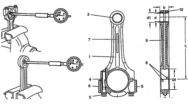
Figure 2.55. Checking the connecting rods.
1. Connecting rod,
2. Connecting rod cover,
3. Connecting rod upper head bushing,
4. Keyway,
5. Bolt,
6. Balance weights,
7. Connecting rod identification surface,
8. Groove for installing the liner,
9, 10. Oil channel,
b. Width of the upper connecting rod head,
B. Width of the lower connecting rod head,
d. Inner diameter of the connecting rod upper head bushing,
d1. Diameter under the bushing in the upper head of the connecting rod,
D1. Connecting rod lower head diameter (with inserts),
L. Distance between the centers of the connecting rod heads.
5. Check the inner diameter of the connecting rod upper head bushing (see figure 2.55). If it is more than the permissible value, replace the bushing.
Installation
6. Installation is carried out in the reverse order of removal.