
Selection of bearing shells
Four cylinder petrol engines
1. To determine the thickness of the required bearing shells, determine the diameter of the shaft journals and the operating clearance in the bearings. The required thickness can be calculated as shown in the example in paragraph 19.
2. Mercedes-Benz dealers or engine rebuilders can supply liners of the required thickness. Refer to the following table showing which earbuds are available.

Six cylinder petrol engines
3. The thickness of the required liners can be determined in the same way as described earlier in paragraph 19 for 4-cylinder petrol engines. At the time of writing the manual, there was no information on the manufactured liners for 6-cylinder gasoline engines. You can consult with Mercedes-Benz dealers. You can also buy liners from them.
Diesel engines
4. The thickness of the required liners can be determined in the same way as described earlier in paragraph 19 for 4-cylinder petrol engines.
5. Your dealer or engine rebuilder can supply you with the required inserts. Refer to step 2 to determine which liners are available.
Checking the operating clearance in connecting rod bearings
6. Clear the back party of loose leaves and surfaces of the lower head of a rod and a cover.
7. Install the bushings into place, making sure that the tabs on each bushing fit into the cutouts on the connecting rod and cap. Do not touch the working surfaces of the earbuds with your fingers. If set for verification "native" connecting rod bearings, make sure they are in their original positions. Clearances can be checked in two ways,
8. To determine the operating clearance, install the connecting rod cap together with the first method. inserts on the connecting rod (check that they are correctly aligned) and measure with an internal micrometer or vernier caliper the inner diameter of the bearing formed by the connecting rod bearings. The difference between the diameter of each pair of bearings and the diameter of the corresponding connecting rod journal of the crankshaft gives the operating clearance of the bearing.
9. The second and more accurate method is to use Plastigauge (see paragraph 19).
10. Make sure the connecting rod bearings are installed correctly. Place a piece of Plastigauge thread on each cleaned crankpin.
11. Establish rods on a cranked shaft and combine with them covers of rods, using tags made at their removal.
12. Tighten nuts of covers of rods and tighten them with demanded effort. Be careful not to dislodge the Plastigauge thread and turn the crankshaft while tightening the caps.
13. Disassemble the nodes without turning the connecting rods. Use the supplied template to determine the operating clearances in bearings.
14. If the gaps are significantly different than expected, this means that the size of the liners is not selected correctly (or the liners are badly worn if used "native" liners). Before changing the size of the earbuds, make sure that there is no oil, dust, etc. between the earbuds. If the Plastigauge strip is not the same width, this may indicate a taper on the crankpin surface.
15. At the end of the work, scrape off all traces of Plastigauge with a fingernail, wooden or plastic scraper.
Final installation of connecting rods with pistons
Note: It is highly recommended that you use new connecting rod bearing cap bolts when finalizing the connecting rods. To perform this operation, you will need a tool to compress the piston tracks.
16. The following steps assume that the main bearing caps are installed (see paragraph 19).
17. Make sure the connecting rod bearings are installed correctly as described earlier. When installing new liners, wash off all traces of protective grease with kerosene. Wipe the bearings and connecting rods dry with a lint-free cloth.
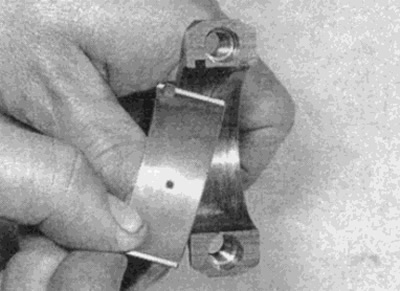
Pic. 20.17. Installing the bushing on the connecting rod
18. Grease a mirror of cylinders, pistons and piston rings, then lay each piston with a rod in the corresponding order.
19. Start with the first node. Make sure the piston rings are positioned as described in paragraph 18. After that, compress them with a ring installer
20. Enter the piston with a rod in the cylinder No. 4. Turn the piston so that the arrow on its bottom is directed towards the gas distribution drive. Using a wooden spacer or hammer handle, carefully push the piston into the cylinder (see fig. 20.20).
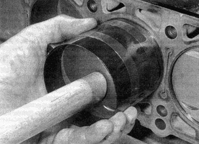
Pic. 20.20. Push the piston into the cylinder with a hammer handle
21. Make sure the connecting rod bearings are in place. Lubricate the crankpin and surfaces of both bearings liberally. Carefully slide the connecting rod down the cylinder to the crank. Install the connecting rod cap, tighten the fastening nuts by hand. Recall that surfaces with labels must match each other (this means that the mounting tabs on the bushings are adjacent to each other).
22. Lightly lubricate the threads of the bolts, then hand-tighten the bolts of the connecting rod bearing caps (see paragraph 16 - on all engines it is recommended to use new bolts).
23. Gradually tighten the bolts to the required torque. Where provided, use two tightening steps (see fig. 20.23). When tightening bolts to a certain angle, it is recommended to use an angle measuring device to improve tightening accuracy. If an angle gauge is not available, apply white paint alignment marks to the bolt and cover; they will allow you to determine the angle to which the bolts are turned.
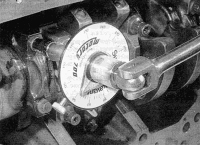
Pic. 20.23. Turning the connecting rod bearing cap bolt
24. When the connecting rod cap nuts are properly tightened, rotate the crankshaft. Make sure it spins freely; if new parts are installed, some force may be required, but there should be no signs of jamming or seizing.
25. In the same way, install the remaining connecting rods with pistons.
26. Perform the following steps according to the type of engine:
- A) On 4-cylinder petrol engines, install the sump and cylinder head as described in Part A of this Chapter.
- b) On B-cylinder gasoline engines, install the oil pump, sump and cylinder head as described in Part B of this Chapter.
- V) On diesel engines, install the oil pump, oil deflector plate (where provided), sump and cylinder head as described in parts of this chapter.