
Checking the axial play of the crankshaft
1. When checking the axial play of the crankshaft, the latter must be installed in the cylinder block, but at the same time it could move freely (see paragraph 12).
2. Measure the axial play using a dial indicator, the tip of which rest against the end of the crankshaft. Move the crankshaft all the way to one side and set the gauge to zero. Move the crankshaft in the opposite direction and determine the amount of axial displacement. The result must be compared with the allowable value given in the technical data. Based on the comparison, it is possible to determine the need to replace the thrust washers (see fig. 15.2). Note that all thrust washers must be the same thickness - refer to the Technical Data section to determine which washers are available.
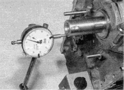
Pic. 15.2. Checking the axial play of the crankshaft using a dial indicator
3. If there is no device, you can use flat probes. Slide the crankshaft all the way towards the flywheel / drive faceplate and, using a feeler gauge, determine the clearance between the thrust washer and crank web No. 3 of the crankshaft connecting rod journal on 4-cylinder engines, between the web No. 4 and the thrust half ring on 5-cylinder engines, and between the web 5 crank and thrust half ring on 6-cylinder engines (see fig. 15.3).
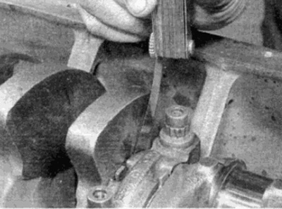
Pic. 15.3. Checking the crankshaft play with a flat feeler gauge
Status check
4. Wash the crankshaft with kerosene or other suitable solvent and dry it well, preferably with compressed air. Pay special attention to ensure that all oil holes are well cleaned.
Warning: Protect your eyes when using compressed air!
5. Carefully inspect the main and connecting rod journals for visible wear, nicks, pitting or cracks.
6. The wear of the connecting rod journals is the cause of a noticeable metallic knock during engine operation, especially distinct during acceleration from low speed, as well as a slight decrease in pressure in the lubrication system.
7. Wear of the main journals causes a strong vibration of the engine, turning into a rumble when the engine is accelerated, and again, a decrease in pressure in the lubrication system.
8. Check for irregularities on the surfaces of the necks by running your finger over them without pressure. In the presence of large irregularities and wear, the crankshaft journals must be ground, if this is still possible, or the entire shaft must be replaced.
9. If the crankshaft has been ground, check for burrs around the crankshaft oil holes (usually the oil holes are chamfered and if the grinding was done properly, burrs are not a problem). Remove any burrs with a fine sandpaper or scraper and clean the oil holes thoroughly as described earlier.
10. Using a micrometer, measure the diameters of the main and connecting rod journals (see fig. 15.10) and compare the measurement results with "technical data". By measuring the diameter of the neck at several points along the circumference, it is possible to determine its ovality. To determine the taper of the neck, measure its diameters at opposite cheeks. Compare measurement results with "technical data". In the absence of data on the wear of the shaft journals in the section "Technical data", consult an engine repair specialist.
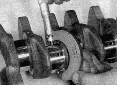
Pic. 15.10. Measure the diameters of the crankshaft journals with a micrometer
11. Look for wear or damage where the crankshaft contacts the seals. If any of the seals has worn a deep groove in the neck, consult an engine repair specialist to see if the shaft can be restored or replacement is required.
12. On some models, if the crankshaft has not been ground, it is possible to restore the crankshaft and install oversized liners (see paragraph 19). If there are no oversized liners and the wear of the crankshaft exceeds the limit established by the technical data, it remains only to replace the shaft. Consult with experts about what details are currently available.