
2. Lay out the pistons with connecting rods and new track sets so that the groups of parts are together during and after checking the gaps in the locks. Lay the cylinder block on its side. to allow access to the cylinders both from above and below.
3. Take the #1 piston top compression ring and insert it from the top into the first cylinder. Push it down with the bottom of the piston - this will ensure that the position of the ring is perpendicular to the walls of the cylinder. Position the ring at the bottom of the cylinder, approximately where it would be when the piston is at bottom dead center. Remember that the top and second compression rings are different. The second compression ring is easily distinguished by the presence of a step on the bottom surface.
4. Measure the thermal gap in the lock of the ring with a feeler gauge.
5. Repeat the measurement in the upper position of the ring (see fig. 18.5). Compare the measurement results with the values in section "Technical data". If the data is not given, consult a specialist.
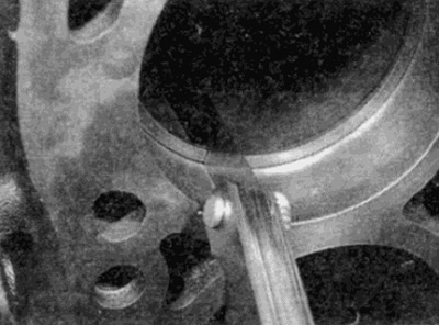
Pic. 18.5. Determination of the gap in the lock of the ring
6. If new rings are installed, too small a gap in the lock should be avoided, otherwise, if the ends of the ring touch during operation, there is a risk of damage to the cylinder mirror. Ideally, the ring should be chosen in such a way that the gap in its lock is equal to the nominal one, but in extreme cases this problem can be solved by filing the ends of the ring with a thin file. Fix the needle file in a vise, spread the ring over the file and slowly move the ring to remove the material from its ends. Be careful - the rings are fragile and have sharp edges.
7. It is also undesirable for the gap in the lock to be too large. If the clearance is large, check that the ring matches the size of your engine's cylinders.
8. Continue the test procedure for all rings of the first cylinder, then the next, and so on. Do not forget to mark the pistons and rings matched to the cylinders.
9. After checking and, if necessary, adjusting the gaps in the locks. rings can be installed in pistons.
10. Install the rings using the same technology. as in removal. Install the bottom oil ring first. When installing the ring, insert the expander, then install the oil scraper ring so that the gap is at an angle of 180°to the gap on the expander. Locate the marking on one side of the second compression ring (either painted or embossed "TOR") and install the ring with this side up and the bevel down (see fig. 18.10, a, b). After installing all the rings, turn their locks at an angle of 120°to each other. Make sure that no ring lock is located above the piston pin hole.
Note: Always follow the instructions that come with new rings - different manufacturers may prescribe different procedures. Do not scare the first and second compression rings - they have a different cross section.
Pic. 18.10, a. Installing the oil ring expander
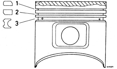
Pic. 18.10, b. Typical arrangement of rings.
1 Oil scraper ring
2 Second compression ring
3 Top compression ring