
Note: A new or remanufactured head can be purchased from service stations and specialists. Since special tools and fixtures are needed to disassemble and inspect the condition of the head and its parts, and in addition, the repair may require some new parts that may not always be available, it may be more practical and cost-effective for the home mechanic to purchase a remanufactured head than disassemble, determine the condition and repair the old one. This operation requires a spring compressor.
Four cylinder petrol engines
1. Remove the cylinder head as described in Part A of this Chapter.
2. Remove the intake and exhaust manifolds as described in Chapter 4.
3. Remove the pusher cam gear, valve lifters and camshaft as described in Part A of this Chapter.
4. If desired, remove the spark plugs from the cylinder head.
5. Where required, remove the thermostat housing from the cylinder head.
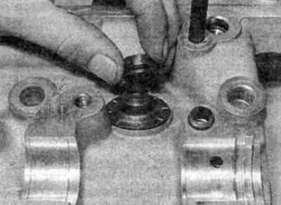
6. Using a valve spring compressor, compress the valve spring and loosen the cotters. Release the spring and remove the spring plate and the spring (see fig. 8.6, a-g).
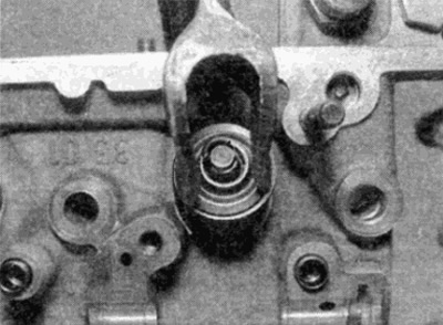
Pic. 8.6, a. Compress the valve spring...
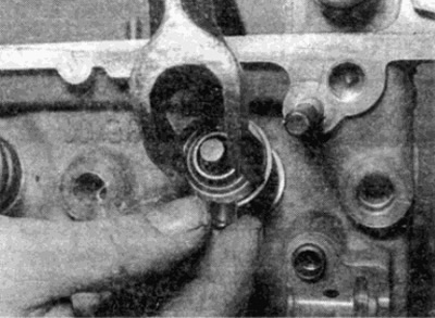
Pic. 8.6b. And take off the crackers
Pic. 8.6, c.... then the spring plate...
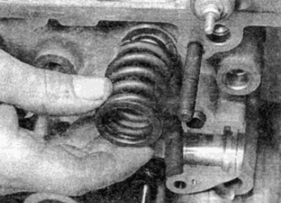
Pic. 8.6, g...and a spring
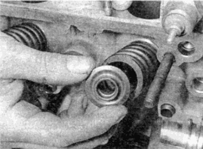
7. Carefully remove the oil deflector caps from the guide bushings with pliers, then the spring plates (see fig. 8.7, a, b).
Pic. 8.7, a. Remove the oil seal
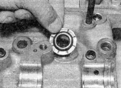
Pic. 8.7b....and a spring plate
8. Remove the valve through the combustion chamber (see fig. 8.8).
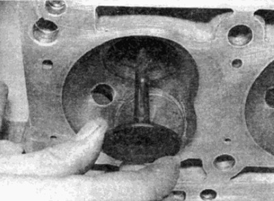
Pic. 8.8. Remove the valve through the combustion chamber
9. The valve, spring, and seats are a set that must not be separated during assembly. In addition, the valves must be stored in the order in which they were installed, unless the valve is replaced with a new one. If the valves are to be used further, it is recommended to store each valve and related parts in a separate plastic bag or similar labeled container (see fig. 8.9).
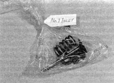
Pic. 8.9. Store each valve and related parts in a labeled plastic bag
Six-cylinder petrol engines
10. Remove the cylinder head as described in Part B of this Chapter.
11. Remove the intake and exhaust manifolds as described in Chapter 4.
12. Remove the pusher cam gear, valve lifters and camshaft as described in Part B of this Chapter.
13. Follow the steps described in p.p. 5-9.
Diesel engines
14. Remove the cylinder head as described in parts of this chapter.
15. Remove the intake and exhaust manifolds as described in Chapter 4.
16. If desired, remove the glow plugs as described in Chapter 5.
17. Follow the steps described in p.p. 5-9.