



Contents: Cleaning ↡ Examination ↡
Cleaning
1. Before checking, the pistons and connecting rods should be washed, and the old rings should be removed from the pistons.
2. Carefully spread the ring by the edges of the gap and remove it from the piston upwards. Two or three old feeler gauges may be useful to prevent the rings being removed from falling into already free grooves (see fig. 14.2). Do not scratch the pistons with the ends of the rings. The rings are made of brittle material and can break if they are spread too wide. In addition, they have sharp edges - protect your hands and fingers. Always remove the rings from the top of the piston. Note that the third ring has an expander. If the rings are to be used, store the rings with the piston. For proper installation, write down how each ring is installed.
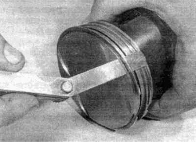
Fig. 14.2. Removing piston rings using feeler gauges
3. Scrape off all traces of carbon deposits from the piston bottom. Any remaining carbon deposits can be removed with a hand carriage or sandpaper.
4. Remove carbon deposits from the grooves using an old ring. To do this, break the ring in half (be careful - the ring has sharp edges). Be careful - remove only carbon deposits, not metal, and do not scratch the walls of the grooves.
5. After removing deposits, wash the pistons and connecting rods with kerosene or other suitable solvent and dry thoroughly. Make sure that the oil drain holes in the oil scraper ring grooves are clean.
Examination
6. If the pistons and cylinder bores are not damaged or too worn, and if the cylinder block does not require boring, the old pistons can be installed during assembly. Measure the piston diameters and check that they are within the appropriate group. If the clearances between the pistons and cylinders are increased, the cylinder block must be bored and new repair pistons and rings must be installed. A normally worn piston has vertical traces of uniform wear on the surface in contact with the cylinder and a slightly worn groove for the upper ring. In any case, install new piston rings when assembling the engine. Recall that the dimensions of the pistons and cylinders are stamped on the piston bottom and on the mating surface of the cylinder block.
7. Carefully inspect the pistons for cracks in the skirt, around the piston pin holes and in the spaces between the grooves.
8. Check for significant wear and tear on the skirt, burnouts on the piston crown, and burn marks around the perimeter of the crown. If there are scratches or scuffs on the skirt, this may mean that the engine is overheating during operation or the combustion process is not normal at high operating temperatures. In this case, it is necessary to carefully check the cooling and lubrication systems. Traces of scuffs on the side surfaces of the piston mean that there was a gas breakthrough between the piston and the cylinder wall. Burnouts and burn marks on the piston crown could have occurred due to combustion process disturbances (incorrectly adjusted ignition timing, detonation). If there are any of the listed problems, it is necessary to find out and eliminate the causes, otherwise the problems will arise again. The reasons may be incorrectly set ignition or intake timing or faulty injectors (diesel engines).
9. Piston pitting means that coolant is leaking into the combustion chamber or crankcase. In this case, it is also necessary to find out and eliminate the cause, otherwise these problems will occur again in the repaired engine.
10. New pistons can be purchased from your Mercedes-Benz dealer.
11. Carefully inspect each connecting rod for damage such as cracks in the top and bottom ends, warping, or warping. Such damage is unlikely unless the engine has been severely overheated or seized. A detailed inspection of the connecting rods can be performed by an engine repair specialist with the special equipment.
12. Floating piston pins are secured against longitudinal displacement by two spring rings. If necessary, they are disassembled in the following order.
13. Using a small screwdriver, remove one of the spring tracks that secure the pin. Push the pin out of the piston and the upper connecting rod head (see Fig. 14.13, a, b). Hand force is enough to remove the pin. Mark the connecting rod and piston to assemble them correctly. New spring rings must be installed during installation.
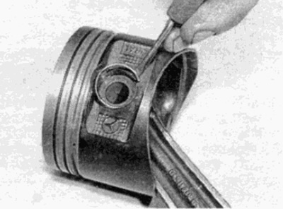
Fig. 14.13,a. Remove the spring ring (16-valve engines)
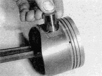
Fig. 14.13.6. ...and push out the piston pin
14. Check the piston pins and connecting rod upper head bushings for wear or damage. Wear can only be eliminated by replacing the pin and bushing. Replacing the connecting rod upper head bushing is a complex operation requiring press equipment.
15. Connecting rods do not require replacement unless there is a seizure or other mechanical failure. Check the straightness of the connecting rod and, if in doubt, seek advice from a specialist.
16. Inspect all parts and, if necessary, purchase new ones. If you purchase new pistons, they should be equipped with new pins with spring rings. Spring rings can also be purchased separately.
17. Position the piston in relation to the connecting rod as follows (see fig 14.17).
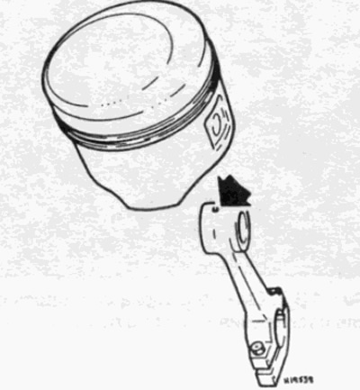
Fig. 14.17. Small hole for lubrication (shown by arrow) must be located on the drive chain side - gasoline engines
- a) On petrol engines, the small lubrication hole in the top of the connecting rod and the arrow on the piston crown must point towards the engine camshaft drive chain.
- b) On diesel engines, the slots for the liners in the connecting rod and bearing caps must be located on the high-pressure pump side and the arrow on the piston bottom must point towards the drive chain.
18. Lubricate the piston pin. Install the connecting rod into the piston and insert the pin. Make sure that the piston rotates freely on the connecting rod. Secure the pin with a spring ring. Position the ring so that its lock faces downwards.