



Removal
Remove the pistons (see section Removal and installation piston rings).
Examination
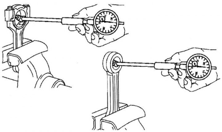
Checking the diameters of the upper and lower connecting rod heads using an indicator
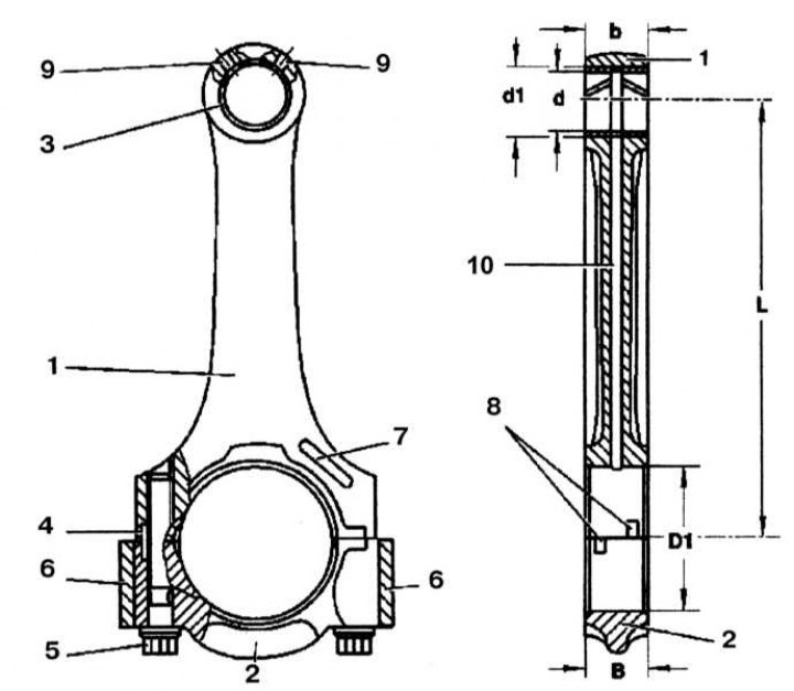
Main dimensions of the connecting rod
1 - Connecting rod; 2 - Connecting rod cover; 3 - Connecting rod upper head bushing; 4 - Keyway; 5 - Connecting rod cover fastening bolt; 6 - Balancing weights; 7 - Connecting rod identification field; 8 - Grooves for installing liners; 9 - Oil channels (engine 902.980); 10 - Oil channel (engine 601.943); "b" - Width of the upper connecting rod head; "B" - Width of the lower connecting rod head; "d" - Inner diameter of the connecting rod upper head bushing; "d1" - Diameter of the hole for the bushing of the upper head of the connecting rod; "D1" - Diameter; "L" - Distance between the centers of the connecting rod heads
1. Check the connecting rods for tarnish, scuffs and scratches.
2. Loosen the mounting bolts and remove the connecting rod caps.
3. Measure the diameters of the lower and upper heads of the connecting rod. If the measured value is greater than the permissible value, grind the contact surface of the connecting rod cap by 0.2 mm.
Note: The connecting rods of the 601.943 engine are similar to those used on non-turbocharged models, 602.980 - with turbocharging. If it is larger than the permissible limit, replace the bushing. The dimensional characteristics of the connecting rods are given in Specifications.
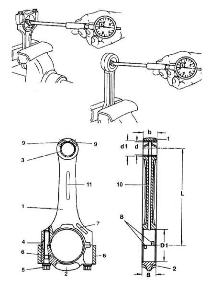
Check the inner diameter of the connecting rod upper head bushing.
[Publication reprinted from this resource: MERCEDESMAN]
Installation
Installation is carried out in the reverse order of removal.