



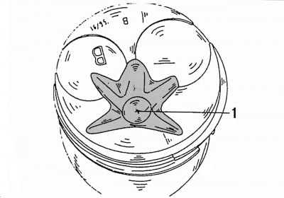
Figure 47. Piston with combustion chamber (1) made on it
The pistons are made of a special aluminum alloy. Each piston has a star-shaped combustion chamber 1 (figure 47) and two round recesses for the valve heads. The neck of the pre-chamber protrudes into the piston combustion chamber. Two round notches (see figure 47) designed for valve plates. They help prevent the piston from hitting the valves.
Three rings are installed on each piston. The top two rings are compression rings; they prevent gases from burning fuel from breaking through into the engine crankcase. The lower ring is an oil scraper and is designed to remove oil from the cylinder walls to prevent it from getting into the fuel combustion zone. The top ring has a rectangular cross-section, the middle ring has an internal chamfer, and the oil scraper ring has a chrome-plated outer surface. Only in this installation sequence are piston rings able to perform their functions. Connecting rods connect the pistons to the crankshaft. The piston pin connects the piston to the connecting rod.
After removing the connecting rod bearing caps and liners, the pistons with connecting rods can be pushed upwards out of the cylinder block using a hammer handle. Before carrying out these works, the following instructions regarding the marking and installation position of the parts must be strictly observed.
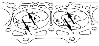
Figure 48. Designations on the piston crowns (arrows B) and cylinder block (arrows A) indicating the piston diameter size groups
Pistons and cylinders are divided into three size groups within certain tolerances and have letter designations A, X and B. These designations are stamped on the cylinder block, next to the cylinder liner, as shown by arrows A in Figure 48. The size group of pistons must correspond to the markings applied next to the cylinders.
In addition to the letter designations, the 7th and 8th digits of the spare part number are also stamped on the piston bottoms. In addition, each piston is marked with an arrow labeled "Vorn" ("Before") to indicate the mounting position of the pistons.
Only pistons with the designation X are supplied for repair. These pistons can be used on engines with cylinder designations A or B.
If there is a need to hone the cylinders, they must be ground to piston size group X, taking into account the prescribed working clearance.
Each piston and its connecting rod must be provided with a mark indicating the cylinder number from which they were removed. This is best done with paint on the piston bottoms; at the same time, you can also apply arrows to indicate the installation position of the pistons, since the factory arrows may not be visible under a layer of carbon deposits.
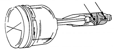
Figure 49. Marking of the connecting rod bearing cap and connecting rod
When dismantling the piston with the connecting rod, it is necessary to mark the mounting position of the connecting rod bearing cap, and after removing the piston with the connecting rod, immediately apply markings indicating the cylinder number. This can be done with a center punch (one center punch mark is the first cylinder, two marks are the second cylinder, etc.), as shown in the figure 49.
Bearing shells should be marked with the connecting rod and connecting rod bearing cap. The upper bearings have holes for lubrication of the piston pin.
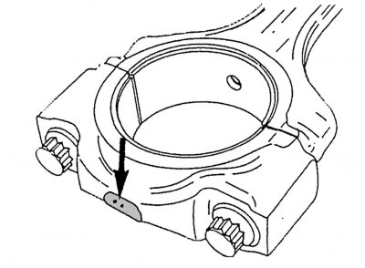
Figure 50. Markings on the bottom of the connecting rods
Connecting rod bearings can have different diameters. On the underside of the connecting rod bearing caps, markings are made with a center punch - one or two marks (figure 50). If there is one mark, the liners with the blue marking applied to the side of the liners should be installed. If there are two marks, as shown in the figure, the inserts without color markings should be installed.
Crankshaft journals can be subjected to four-fold grinding. Accordingly, appropriate bearing shells must be installed, which are produced in repair sizes that differ by 0.25 mm.
Remove the bearing caps and liners, push the pistons with connecting rods out of the cylinders. If necessary, use a scraper to remove the carbon deposits that have formed on the top of the cylinders.
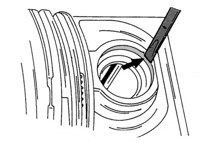
Figure 51. Removing the piston pin retaining ring
After removing the retaining rings, push out the piston pin. The notches in the piston bosses allow you to use a screwdriver (the tip of the screwdriver must be inserted next to the joint of the retaining ring) or a thin punch for removing piston pin retaining rings (figure 51). Press out the piston pin using a suitable mandrel.
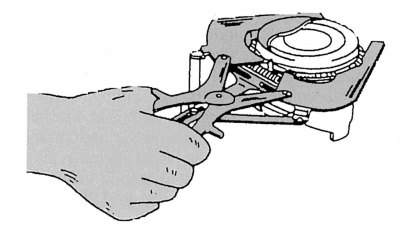
Figure 52. Removing and installing piston rings
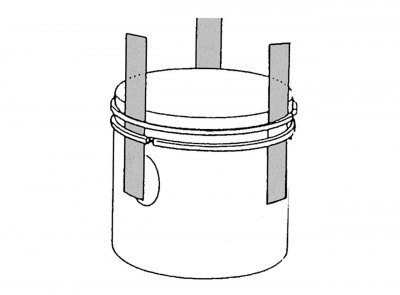
Figure 53. Using metal plates to remove and install piston rings
Remove the piston rings one by one using special pliers, as shown in the figure 52. If piston rings are to be reused, they must be marked accordingly. If you do not have piston ring pliers, you can use metal plates inserted under the piston rings from opposite sides, as shown in the picture 53. One of the plates must be inserted under the piston ring in the lock area to avoid scratching the piston. Figure 54 shows the parts after disassembling the piston with the connecting rod.
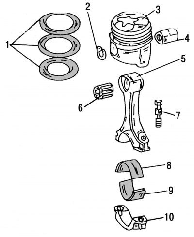
Figure 54. Piston and connecting rod after disassembly: 1 - piston rings; 2 - piston pin retaining rings; 3 — piston; 4 - piston pin; 5 — connecting rod; 6 - bearing sleeve in the upper head of the connecting rod; 7 — connecting rod bearing cap mounting bolts; 8 — upper connecting rod bearing shell; 9 — lower connecting rod bearing shell; 10 — connecting rod bearing cap