



Contents: Disconnection ↡ Connection ↡
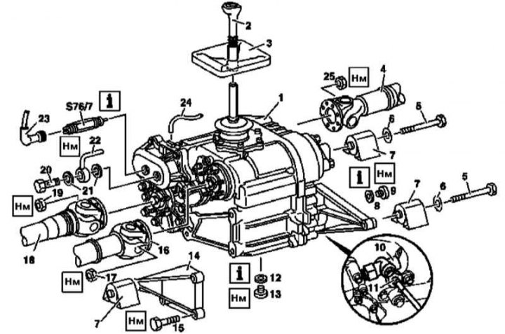
Transfer case installation details (using the 750.653 series as an example)
1 - Transfer case; 2 - Shift lever*; 3 - Dust cover*; 4, 16, 18 - Cardan shafts; 5, 15 - Screws; 6 - Washer; 7 - Rubber cushions; 8, 12 - Sealing rings; 9 - Filler plug; 10 - Angular drive*; 11 - Speedometer drive shaft*; 13 - Drain plug; 14 - Support lever; 17, 19, 25 - Nuts; 20 - Hollow bolt of nipple connection; 21 - Sealing washers; 22 - Pneumatic tract line; 23 - Connector; 24 - Pumping line; S76/7 - Center differential lock indicator switch
*Not available on the models in question
Disconnection
Front axle drive output shaft
1. Move the AT selector lever to the "N" position, engage the transfer case in road driving mode.
2. Jack up the car and lift the left front wheel.
3. Rotate the suspended wheel, unbolt the cardan shaft (18), move it to the side and tie it up.
Transfer case drive shaft
1. Move the AT and transfer case to neutral positions.
2. Rotate the drive shaft (16), loosen it, move it to the side and tie it up.
Rear axle drive output shaft
1. Move the AT selector lever to the "N" position, engage the transfer case in road driving mode.
2. Jack up the car and lift the left rear wheel.
3. Rotate the suspended wheel, unbolt the cardan shaft (4), move it to the side and tie it up.
Connection
Attention! The driveshaft fastening nuts must be replaced without fail!
1. Turn the input flange on the transfer case with the yellow mark facing down.
2. With the cardan shafts facing up with the green marks, connect them to their flanges on the transfer case.
3. Make sure the NEW mounting nuts are tightened to the required torque.