
Transfer box installation details (on the example of series 750.653)
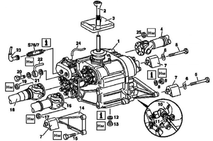
1 - Transfer box; 2 - Switching lever *; 3 - Dust cover*; 4, 16, 18 - Cardan shafts; 5, 15 - Screws; 6 - Washer; 7 - Rubber cushions; 8, 12 - O-rings; 9 - Filler plug; 10 - Angle drive *; 11 - Speedometer drive shaft *; 13 - Drain plug; 14 - Support arm; 17, 19, 25 - Nuts; 20 - Hollow bolt of choke connection; 21 - Sealing washers; 22 - Pneumatic path line; 23 - Connector; 24 - Pumping line; S76 / 7 - Sensor-switch of the center differential lock indicator
1. Disconnect the electrical wiring and remove the transfer box servomotor (see Section Removal and installation of the transfer box servomotor).
2. Disconnect from transfer case (1) cardan shafts (4, 16 and 18) (see Section Disconnection and connection of cardan shafts on the transfer case), nuts (17, 19 and 25) must be replaced without fail.
3. Using a suitable socket wrench, remove the differential lock indicator switch (S76/7).
4. Turn out the filler (9) and drain (13) plugs and release gear oil into the prepared container.
5. Jack up the transfer case (1) from below, completely unloading the rubber cushions (7) its suspension mounts.
6. Detach the support arm from the front (14), remove the rubber pads (7) rear, slightly lower the right side of the transfer case, turn the left side forward and remove. Check the condition of the rubber pads (7), replace them if necessary.
7. Installation is carried out in the reverse order. Make sure that all fasteners are tightened to the required torque, do not forget to replace the o-rings (8 and 12).