
General information
The torque developed by the engine is transmitted through the AT to the transfer case equipped with an interaxle differential and from there, by means of cardan shafts, to the differentials of the front and rear axle assemblies.
On all models considered in this Manual, the all-wheel drive is made non-switchable. The design of the two-stage transfer case provides for a center differential lock mechanism. The transfer case gearbox is fully synchronized, so that gear shifting can be done while driving. There are also mechanisms for forced locking of both cross-axle differentials.
Differential Lock Order
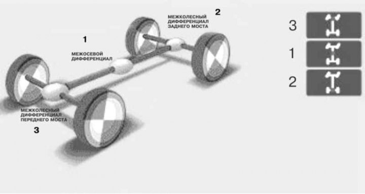
The differential lock is controlled by switches mounted in the central part of the instrument panel of the car (see Section Controls and interior equipment). Blocking must be carried out strictly in a certain sequence: INTERAXIAL DIFFERENTIAL —› REAR AXLE —› FRONT AXLE. The differential lock should only be engaged in difficult terrain, when driving through water, or on roads covered in snow, ice, or mud.
Unlike cars with plug-in all-wheel drive, here the torque is constantly transmitted to both axles. The redistribution of power between the axles is provided by the center differential. The mode of rigid connection between the axles, necessary to achieve maximum traction, is provided by blocking this differential.
The advantages of permanent all-wheel drive include the stability of the car's handling characteristics, the ability to use the lower row of the transfer case without blocking, and therefore, on any roads without traction restrictions. In addition, such a car is always in a state of «high combat readiness». Forced differential lock can be used as an additional means of improving cross-country ability in case of off-road problems. It should be noted that maximum traction with poor ground grip can only be obtained through forced blocking, since any automation involves wheel slip (if there is no slip, then the lock does not work), which inevitably leads to loss of tractive effort
Not without permanent four-wheel drive and disadvantages. After all, such a car has to turn all the cardan shafts and axle shafts. As a result, on the pavement, its transmission is as noisy as the plug-in all-wheel drive with the wheel couplings engaged, and also provides «all-wheel drive» increase in fuel consumption.
Nevertheless, permanent all-wheel drive still provides more positives than negatives, especially for real SUVs.
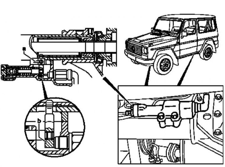
Differential lock controls
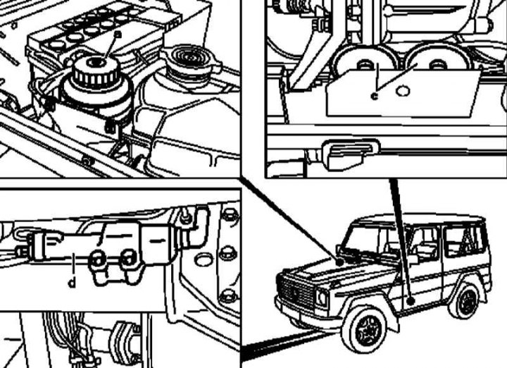
a - Reservoir; c - Pressure blocks for switching the interwheel differential locks of the front and rear axle assemblies; d - Actuating cylinders for switching the interwheel differential locks of the front and rear axle assemblies
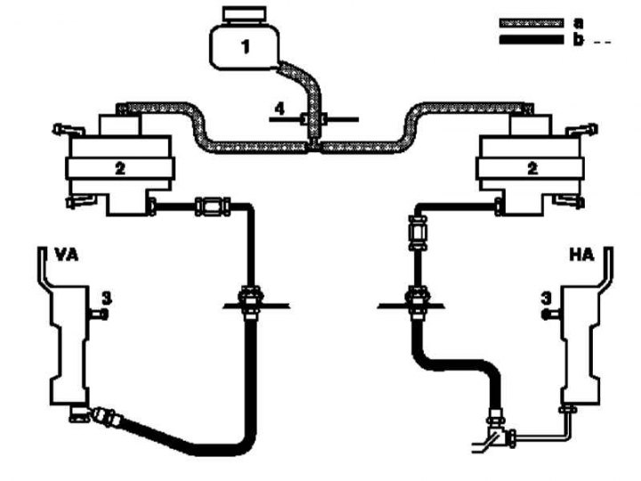
Functional diagram of the differential lock hydraulic drive
1 - Reservoir; 2 - Pressure blocks for switching interwheel differential locks assemblies of the front and rear axles; 3 - Executive cylinders for switching the interwheel differential locks of the front (VA) and rear (HA) bridges; 4 - Arch of the right wheel; a - Hydraulic fluid supply circuit; b - Working circuits of the actuating cylinders
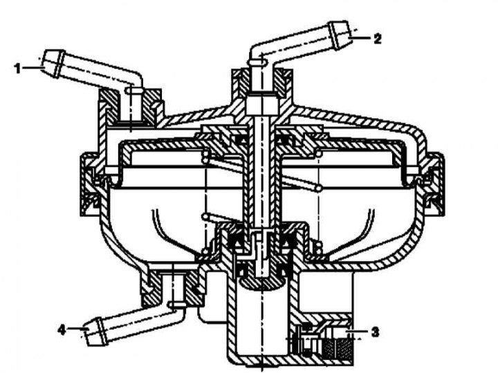
The design of the hydropneumatic pressure block
1 - Air access; 2 - To the hydraulic fluid reservoir; 3 - To the executive cylinder of the blocking control mechanism; 4 - Suction fitting (underpressure)
The layout of the mechanical components of the control blocking cross-axle differentials
a - Bridge crankcase ventilation breather; b - Switch finger
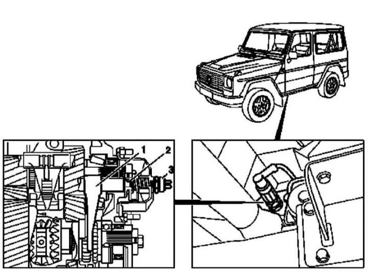
The layout of the mechanical components of the center differential lock control
1 - Switch fork; 2 - Executive cylinder; 3 - Control switch (S76/2)
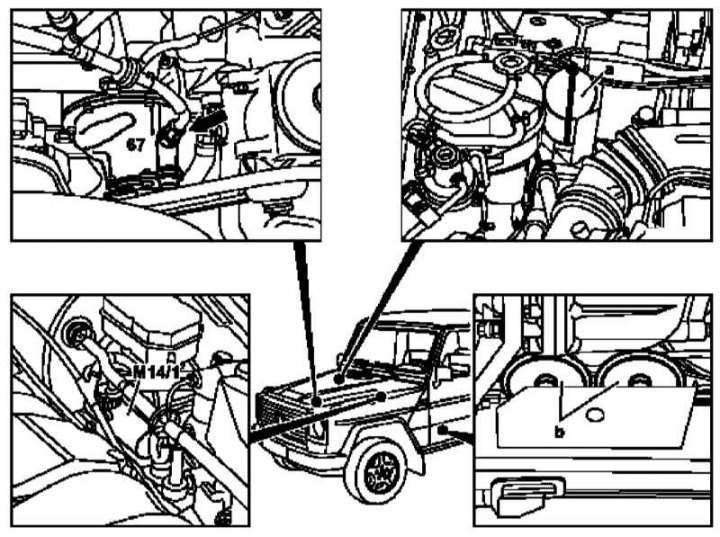
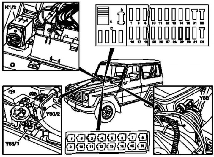
Layout diagram of pneumatic components for differential lock control
M14/1 - Auxiliary vacuum pump (petrol models); 67 - Vacuum pump (diesel models); a - Vacuum receiver (0.4 l); b - Pressure blocks for switching the interwheel differential locks of the front and rear axle assemblies
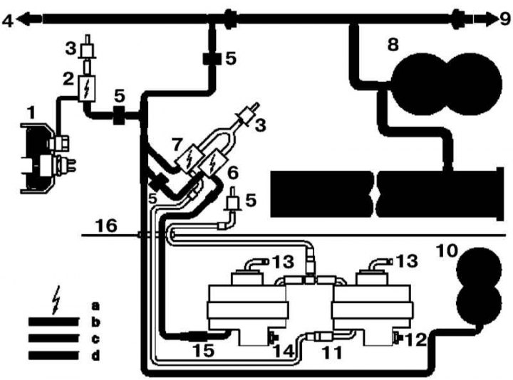
Functional diagram of the differential lock pneumatic drive on DIESEL models (locks of center differential and interwheel differential of the rear axle are included
a - The element is activated; b - Switching pressure; c - Supply pressure; d - Hydraulic pressure; 1 - Transfer case (center differential); 2 - Solenoid valve (Y68) switching center differential lock; 3 - Replaceable filter of the solenoid valve; 4 - To the vacuum pump; 5 - Control valve; 6 - Solenoid valve (Y68/1) switching the interwheel differential lock of the rear axle; 7 - Solenoid valve (Y68/2) switching of blocking of cross-axle differential of the forward bridge; 8 - Vacuum reservoir of the brake system in the cross beam of the frame: 4.4 l (auxiliary vacuum reservoir: 1.8 l); 9 - To the servo drive of the vacuum brake booster; 10 - Vacuum reservoir for differential lock (0.4 l); 11 - Pressure block for switching the interwheel differential lock of the front axle; 12 - Fitting of the hydraulic path for controlling the blocking of the center differential of the front axle; 13 - To the hydraulic fluid reservoir; 14 - Fitting of the hydraulic circuit for controlling the blocking of the center differential of the rear axle; 15 - Pressure block for switching the interwheel differential lock of the rear axle; 16 - Right wheel arch
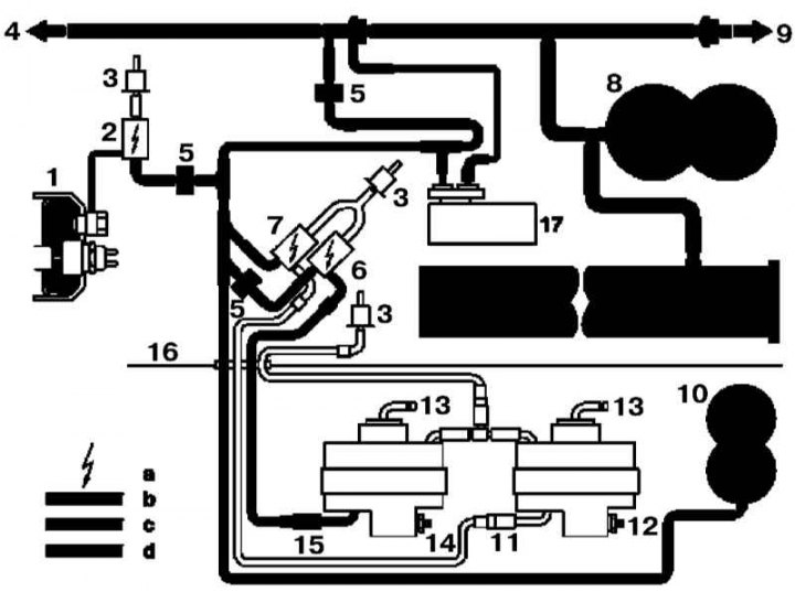
Functional diagram of the differential lock pneumatic drive on PETROL models (locks of center differential and interwheel differential of the rear axle are included
a - The element is activated; b - Switching pressure; c - Supply pressure; d - Hydraulic pressure; 1 - Transfer case (center differential); 2 - Solenoid valve (Y68) switching center differential lock; 3 - Replaceable filter of the solenoid valve; 4 - To the inlet pipeline; 5 - Control valve; 6 - Solenoid valve (Y68/1) switching the interwheel differential lock of the rear axle; 7 - Solenoid valve (Y68/2) switching of blocking of cross-axle differential of the forward bridge; 8 - Vacuum reservoir of the brake system in the cross beam of the frame: 4.4 l (auxiliary vacuum reservoir: 1.8 l); 9 - To the servo drive of the vacuum brake booster; 10 - Vacuum reservoir for differential lock (0.4 l); 11 - Pressure block for switching the interwheel differential lock of the front axle; 12 - Fitting of the hydraulic path for controlling the blocking of the center differential of the front axle; 13 - To the hydraulic fluid reservoir; 14 - - Fitting of the hydraulic path for controlling the blocking of the center differential of the rear axle; 15 - Pressure block for switching the interwheel differential lock of the rear axle; 16 - Arch of the right wheel; 17 - Auxiliary electric vacuum pump (М14/1)
The layout of the electrical components of the differential lock control (1 of 2)
1 - Switch for locking the center differential; 1.1 - Control lamp for locking on (yellow); 1.2 - Control lamp for blocking operation (red); 2 - Switch for blocking the cross-axle differential of the rear axle; 2.1 - Control lamp for locking on (yellow); 2.2 - Control lamp for blocking operation (red); 3 - Switch for blocking the interwheel differential of the front axle; 3.1 - Control lamp for locking on (yellow); 3.2 - Control lamp for blocking operation (red); N30/2 - Differential lock control module; S76 / 2 - Control sensor-switch for locking the center differential; S76 / 3 - Control sensor-switch for blocking the cross-axle differential of the rear axle; S76 / 4 - Control sensor-switch for blocking the cross-axle differential of the front axle

The layout of the electrical components of the differential lock control (2 of 2)
3 - Relay (K36) activation of the auxiliary electric vacuum pump (М14/1) on petrol models; 29, 30 - Fuses; K1/1 = K1/2 (diesel models); K1/2 - Electrical overload protection (petrol models); Y68 - Solenoid valve for switching center differential lock; Y68 / 1 - Solenoid valve for switching the interwheel differential lock of the rear axle; Y68 / 2 - Solenoid valve for switching the front axle differential lock