
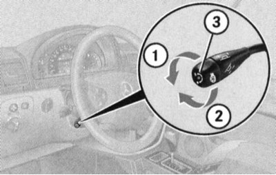
Combined steering column switch
Switching the operating modes of the headlights, high beam signaling
Note. Activation of high beam in continuous mode) Only possible with headlights on (see below).
With the help of the steering column switch, the headlights can be switched from the low beam mode to the high beam mode, - press the lever away from you, - the corresponding control lamp of a characteristic blue glow should light up automatically on the instrument panel (see Section Instrument cluster, meters, control lamps and indicator lights). To turn off the high beam, return the lever to its original position.
Switching the operating modes of the headlights
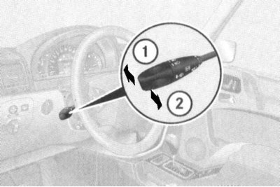
1 - Position «high beam»
2 - high beam signaling
The possibility of high beam signaling is also provided: the signaling is carried out by pulling the stalk lever towards you and regardless of the selected position of the handle for selecting the mode of operation of the external lighting devices (see below).
Note. High beam signaling can be done even when the ignition is off.
Turn signal activation
The direction indicators are activated by pushing the stalk lever in the appropriate direction. The lever is moved up or down, depending on the selected direction of change of course.
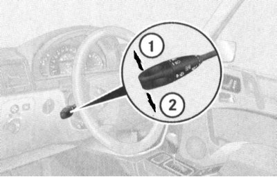
1 - Activation of right turn indicators
2 - Activation of left turn indicators
When moving the lever to the extreme (click) up/down position the corresponding direction indicators will continue to function until the steering wheel is returned to the straight-ahead position (the limit switch will work), or until the lever is forcibly returned to the neutral position.
Note. Short-term inclusion of pointers, for example, with the intention to change the lane of movement, is done by slightly pulling the lever up or down.
Windshield wiper/washer control
Note. Activation of windshield wipers and washers and headlight lenses is only possible with the ignition on (key in position 1 or 2).
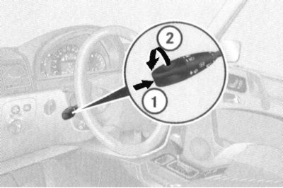
1 - Single activation of the wipers / washer fluid supply
2 - Activation / selection of the operating mode of the wipers
The choice of the operating mode of the wipers is made by turning the rotary handle of the switch lever:
0: Off
I: Interval mode (the duration of the pause is determined by the readings of the rain sensor; when the car is stopped and the front door is opened, the movement of the wipers stops in order to prevent the ingress of the wiped moisture on the clothes of the driver / passenger leaving the passenger compartment)
II: Normal speed continuous wiper
III: High speed continuous wipers (when the car is stopped, it automatically switches to normal mode)
A single operation of the wipers can be performed by briefly pressing the switch handle.
The washer fluid supply is activated by pressing the switch handle (1) with overcoming the point of resistance, - the supply of washer fluid is accompanied by several strokes of the wiper blades.
Note. When the car comes to a complete stop and one of the front doors is open, the intermittent operation of the wipers is suspended, which helps prevent the moisture brushed off from getting on the clothes of the driver / passenger entering or leaving the car.
Steering column switch for speed control/Speedtronic variable speed limiter
The lever switch for controlling the functioning of the tempostat is located on the steering column above the combined steering column switch (see illustration The layout of the control components on the instrument panel and steering column).
A detailed description of the principles of controlling the functioning of the tempostat is given in Section Speed control systems (Tempostat/Speedtronic).
Steering wheel adjustment/heating switch
Steering wheel adjustment
Attention! To avoid losing control of the steering wheel, the steering wheel must never be adjusted while driving!
The steering wheel adjustment lever switch is located on the left side of the steering column below the combination stalk (see illustration The layout of the control components on the instrument panel and steering column). Adjustment can be made for another 30 minutes after the key is removed from the ignition, provided that the driver's door is open.
Turn on the ignition, or open the driver's door.
The column length is adjusted by pushing/pulling the lever forward/back. To adjust the height of the steering wheel, the lever must be moved up or down in the vertical plane.
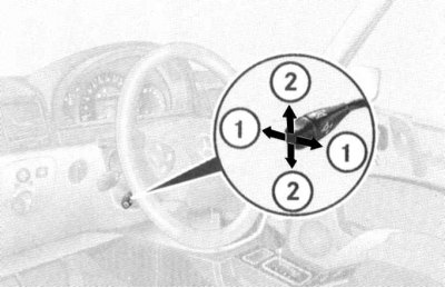
1 - Adjusting the length of the protrusion of the steering column
2 - Adjusting the height of the steering wheel
The selected position of the steering wheel is stored in the memory of the processor at the same time as storing the position of the driver's seat.
Heating
Note. The heated steering wheel only functions in positions 1 and 2 of the ignition lock.
At the end of the lever is placed a rotary knob for activating the steering wheel heating, equipped with a built-in control lamp. Turning the handle in the direction of the arrow (1) leads to the activation of the heating elements mounted in the leather-covered segments of the steering wheel rim - at the same time the control LED is activated (3). To turn off the heating, turn the knob in the opposite direction.
Note. Automatic deactivation of the steering wheel heating is not included in its electrical circuit.
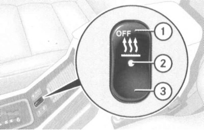
Activate/deactivate steering wheel heating
1 - Turn on
2 - Shutdown
3 - Control lamp
Steering column switch for controlling the operation of the Linguatronic system
Lever switch for controlling the functioning of the Linguatronic system (voice control of certain comfort functions) fits on the right side of the steering column (see illustration The layout of the control components on the instrument panel and steering column).
Voice control is in German, the description of the principle of operation of the system is given in a separate manual.
Horn activation button
The horn button is integrated into the steering wheel hub (see illustration The layout of the control components on the instrument panel and steering column).
On-board computer control panel / audio volume control
The control panels are mounted on the sides of the steering wheel hub and are equipped with push-button switches for selecting modes and switching functions of the on-board computer / audio system control (see illustration Layout of the control components on the multifunction steering wheel). See below for details.
Switches and controls located on the instrument panel
Left switch panel
Door mirror adjustment switch group
The outside rear-view mirrors are spherical in design to widen the field of vision.
The heated mirrors are activated automatically depending on the outside temperature.
There is also an auto-dimming rear-view mirror function (both external and internal) when the headlights of other vehicles participating in the road hit the sensors built into the mirror assemblies (ignition must be on).
Note. Dimming mirrors is not activated when the interior lighting is on, as well as when reverse gear AT is selected («R»).
A group of three switches for adjusting the outside rear-view mirrors is located in the upper left corner of the panel. Adjustment is made using a rotary control switch, directly below which are two push-button switches for selecting the mirror to be adjusted.
Door mirror adjustment
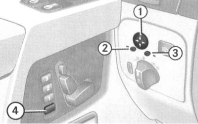
1 - Rotary control switch
2 — The selector switch of adjustment of the left mirror
3 — The selector switch of adjustment of the right mirror
4 - Button for accessing processor memory (for the record)
Recording the selected position of the rear-view mirrors in the memory of the processor is carried out simultaneously with recording the parameters for adjusting the front seats.
The design of the system allows you to record the parking position of the rear-view mirror of the right door. Park the car motionless at the edge of the pavement and leave the ignition on. Make sure that in the settings of the on-board computer is activated («ON») corresponding function (function «MIRROR SETTING WHEN PARKING» in the submenu «CONVENIENCE») (see below), adjust the right door mirror so that it reflects the curbstone and the rear wheel of the car, then press the processor memory access button and press the power mirror control rotary switch down for about 3 seconds, the mirror should not measure its position, otherwise the procedure should be repeated. Now, before starting to park the car, it will be enough to turn on the reverse gear («R») and press the appropriate button on the right door mirror adjustment selector switch. The mirror returns to its original position automatically approximately 10 seconds after the reverse gear is disengaged, when the speed reaches 10 km / h, and also when the selector switch for activating the electric drive of the right door mirror is pressed.
Headlight washer switch
Note. The operation of the headlamp cleaners is possible only when the ignition is on.
The headlight washer activation button is located in the upper right corner of the left switch panel. When the button is pressed briefly, a high-pressure jet of windshield washer fluid is applied to the headlight lenses.
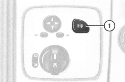
Washer activation switch (1)
Switch for selecting the mode of operation of external lighting devices
The rotary switch handle is located at the bottom of the left switch panel. With a switch. one of the following modes of operation of outdoor lighting devices can be selected:
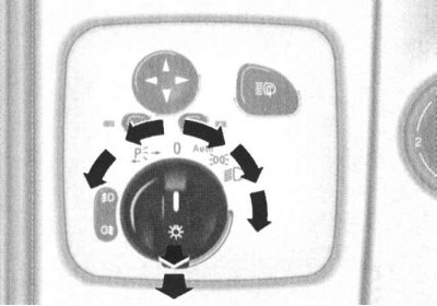
Switch for selecting the mode of operation of external lighting devices
Attention! In countries where DRL activation is legal, this function must not be disabled!
Attention! Dazzling the car with the headlights of oncoming traffic participants can lead to a short-term shutdown of the lighting, which is why the automatic mode should not be used when driving at night! Remember also that the activation of the fog lights in automatic mode is not performed!
To activate the fog lights, turn the knob to the low beam position (
Exterior lighting off delay
Note. Switching on / off and selection of operating settings for the lighting off delay function is done through the menu system of the on-board computer (see below).
After turning off the engine at night, the following exterior lights remain on:
- Parking lights;
- License plate illumination;
- Fog lights.
When the door is opened and then closed, the on-board computer starts a countdown of the selected delay. After this time, the lighting turns off.
Within the next ten minutes, this function can be activated again, for which it is enough to open any of the doors. If, after turning off the engine, none of the doors is opened or closed, the final shutdown of the external lighting will occur after 15÷60 seconds (depending on the settings entered through the on-board computer menu).
To temporarily deactivate the function, turn the key in the ignition switch to position 0, then to position 2, then back to position 0 after the engine is switched off. The next time the engine is started, the function is automatically reactivated.
Side lighting
When the on-board lighting function is on, unlocking the car with the remote control of a single lock at night leads to the activation of the following lighting devices:
- Parking lights;
- License plate illumination;
- Fog lights;
- Repeaters built into the door mirrors.
The backlight turns off automatically when the driver's door is opened (except for mirror mounted repeaters), when the ignition is switched on, as well as by a timer after a maximum of 40 seconds. Opening any of the front doors deactivates only the mirror repeater of the same name.
Headlight beam tilt adjuster
The rotary handle of the headlight beam tilt adjustment switch is located on the left side of the instrument panel in close proximity to the steering column (see illustration The layout of the control components on the instrument panel and steering column) and has six fixed positions (0, 1, 2, 3, 4 and 5).
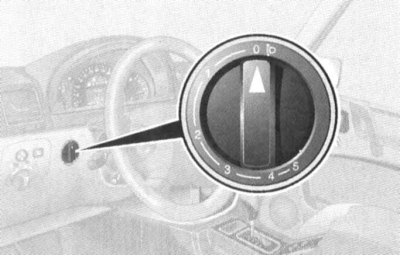
Headlight beam tilt adjuster
The switch serves to adjust the length of the dipped-beam illumination zone in order to prevent dazzling of oncoming drivers, as well as vehicles in front.
The regulator must be set to a position corresponding to the number of passengers and the degree of vehicle loading (see Specifications).
Ignition switch/steering column lock
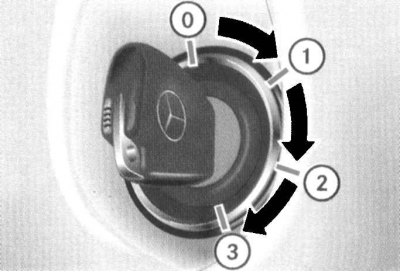
The ignition lock has four fixed positions
The ignition lock is located on the instrument panel, to the right of the steering column (see illustration The layout of the control components on the instrument panel and steering column). The key can occupy one of four fixed positions in the lock:
0: Key removal/Steering column lock
1: Auxiliary consumers of electricity (parking position)
2: Ignition on/Driving
3: Engine starting
Position 0 - steering column lock
The key can only be entered or removed from the lock in this position. Turning the ignition key from position 0 to position 1 unlocks the steering column. In addition, additional conditions for allowing the removal of the key include the mandatory transfer of the AT selector lever to the position «R» and releasing the foot brake pedal.
The steering column is locked automatically when you try to turn the steering wheel after removing the key from the ignition.
The steering column lock sometimes results in the inability to turn the key in the ignition. In such a situation, turn the steering wheel slightly in one direction or another (in order to relieve the burden), while turning the key in the lock.
Attention! In no case do not remove the key from the ignition while driving - this will inevitably lead to steering column lock and loss of control!. Remove the key from the lock only after the vehicle has come to a complete stop!
Note. The ability to adjust the seats and steering column with the front door open remains for about half an hour after removing the key from the ignition.
Position 1 - parking
In this position of the key, the possibility of functioning of auxiliary consumers of electricity is ensured (audio system, cigarette lighter, heater fan, windshield wipers, etc.).
Position 2 - ignition on/driving
In this position, the ignition key is constantly while the car is moving, as well as when the engine is idling. On diesel models, turning the key to position 2 before starting the engine activates the preheating system. At the same time, electrical power is provided to all systems and additional equipment installed on the vehicle. When the key is turned from position 1 to position 2, some of the control lamps located on the dashboard of the car briefly turn on, confirming that the corresponding systems are functioning correctly (see Section Instrument cluster, meters, control lamps and indicator lights).
Position 3 - start
Turning the key to this position engages the starter. After starting the engine, the key must be released and it will automatically return to position 2.
Hood latch release lever
The hood release lever is located under the instrument panel to the left of the steering column and is painted red.
Differential lock switches
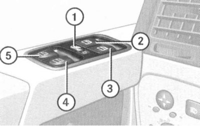
The group of differential lock switches is located in the central part of the instrument panel above its console section between the deflectors of the central air ducts of the interior heating / ventilation systems. Under the switches there are yellow control LEDs for switching on the interlocks, on top - red light indicators for the functioning of the interlocks (see illustration The layout of the control components on the instrument panel and steering column).
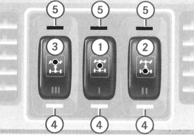
1 - Switch for locking the center differential; 2 - Front axle differential lock switch; 3 - Switch for blocking the cross-axle differential of the rear axle; 4 - Control indicators for the inclusion of differential locks (yellow); 5 - Signal indicators of blocking functioning (red)
The design of the transmission line allows a total of three differentials to be locked: an interaxle differential in the transfer case and two interwheel differentials (in assemblies of both of the bridges).
Attention! Blocking can only be carried out in the sequence 1—›2—›3!
The differential lock allows you to optimize the transfer of traction in off-road conditions when overcoming water obstacles, as well as when driving on snowy and icy roads. The differential lock also allows you to disable the functioning of the ABS and ESP systems in off-road conditions. When starting off with locked differentials, try not to depress the gas pedal abruptly.
Attention! Blocking the cross-axle differential of the front axle significantly reduces the controllability of the car when passing sharp turns!
Blocking should be used only at minimum speeds and in case. Inclusion of blockings should be made only on the standing motionless car.
Center differential lock
The lock is activated by pressing the lower part of the pushbutton switch (1) - the yellow control LED should light up from below, and the 4-ETS/ESP warning lamp in the instrument cluster should be activated (see Section Instrument cluster, meters, control lamps and indicator lights). At the same time, an ABS warning is displayed on the multifunction display («ABS NOT AVAILABLE LOCK SELECTED»). The red control LED above the switch button is activated only after the end of the differential lock process, - the control lamps
Attention! Activating the differential lock will automatically deactivate the ABS, ESP and BAS systems!
After the process of blocking the interaxle differential is completed, sequential blocking of the interwheel differentials can be performed first at the rear, then at the front axle (see below).
Blocking cross-axle differentials
Blocking of cross-axle differentials is carried out using individual switches (2) And (3), - first, the yellow control LED lights up under the corresponding switch, then (upon completion of the blocking process) red on top.
Disable differential lock
To disable the lock, just press the button of the corresponding switch again.
Disabling the differential lock must be done in the reverse order of their inclusion, i.e.: 3—›2—›1!
Simultaneous disengagement of the locks of all differentials can be done by pressing the switch button (1).
The control LEDs should go out. After approximately three seconds of driving in normal mode, the ESP, BAS and ABS systems are automatically activated (indicator lamps
If, after performing the procedure for disabling the locks, the red control LEDs above the switches do not go out, you should slightly change the direction of the car by slightly turning the steering wheel - try not to create emergency situations on the road.
Instrument panel console section switches
Hazard switch
The alarm is activated using a button located in the center at the top of the console section of the instrument panel (see illustration The layout of the control components on the console section of the instrument panel). The switch button is equipped as standard with a built-in signal lamp with a pictogram depicting two triangles inscribed in each other.
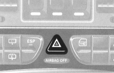
Hazard switch
Turning on the alarm leads to the simultaneous operation of all four direction indicators (and their indicator lights on the vehicle's instrument cluster). The alarm system is designed to warn other road users about the forced stop of the car and is also used in other dangerous situations provided for by traffic rules. To turn off the alarm, press the switch button again.
Note. The alarm is activated automatically when any of the airbags is deployed.
Left upper group of switches
The left upper group of switches of the console section of the instrument panel includes switches for activating the driver's seat heating, activating the rear window wiper / washer and deactivating the anti-skid system (ESP) (see illustration The layout of the control components on the console section of the instrument panel).
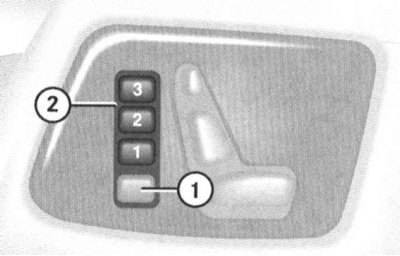
Driver's seat heating activation switches
The buttons for selecting the operating modes of the heating elements of the driver's seat are mounted in the left side of the upper left group of switches in the console section of the instrument panel (see illustration The layout of the control components on the console section of the instrument panel). The heating activation/deactivation principle is the same as described below for the front passenger seat.
Switches for activating the rear window wiper/washer
Note. The rear wiper is activated automatically if the windshield wipers turn on when the (see above) reverse gear («R»).
Two buttons one above the other for activating the cleaner and for supplying washer fluid are located in the central part of the upper left group of switches (see illustration The layout of the control components on the console section of the instrument panel). Make sure the ignition is on. To start the wiper in interval mode, press the top button switch (1), - the control LED built into the panel between the buttons of the switches should light up (2). The wiper is turned off by pressing the same button again - the LED should turn off.
Switches for activating the rear window wiper/washer
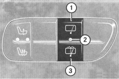
1 - Button for activating the rear wiper in interval mode
2 - Control LED
3 - Button to activate the supply of washer fluid
Pressing the bottom pushbutton (3) washer fluid pump activated on the rear window (with simultaneous start of the windshield wiper), - after the button is released, the fluid supply will stop, and the wiper will continue to operate for about five more seconds.
Anti-skid switch (ESP)
Anti-skid switch (ESP) is located in the center of the lower row of switches in the console section of the instrument panel (see illustration Layout of the control components on the multifunction steering wheel). The need to disable the ESP system may arise when driving with snow chains, in deep snow, sand or gravel. In this case, the engine torque is no longer controlled and the slipping of the drive wheels can have a milling effect on the ground.
To disable the ESP, press the upper part of the switch button - the corresponding control lamp should light up on the instrument cluster (see Section Instrument cluster, meters, control lamps and indicator lights).
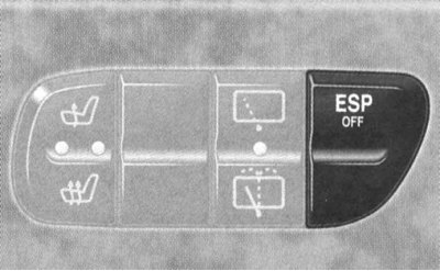
Anti-skid switch (ESP)
To return to normal driving mode, just press the bottom of the button.
Right upper group of switches
The left upper group of switches of the console section of the instrument panel includes switches for activating a single lock, anti-towing systems and ultrasonic scanning of the internal volume, as well as heating the right front seat (see illustration The layout of the control components on the console section of the instrument panel).
Single lock activation switch
It is possible to control the functioning of the lock activators using a key switch mounted in the upper right corner of the console section of the instrument panel (see illustration The layout of the control components on the console section of the instrument panel).
The stationary switch of a single lock is placed on the panel of the center console of the car
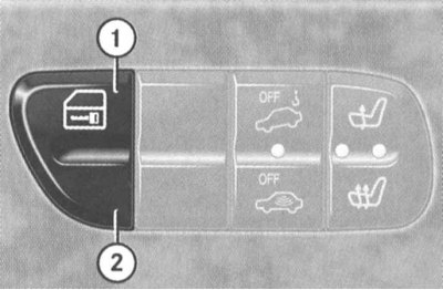
1 - Button for locking locks
2 — The button of unlocking of locks
Note. If the locks were locked using the remote control, unlocking them using the console switch is not possible. Locking the locks with the console switch can only be done with all the doors of the car tightly closed.
Switches for activating special anti-theft alarm modes (towing protection and ultrasonic interior scanning)
Location of the control LED for activation of the anti-theft system and switches for special modes of the anti-theft system (see also illustration Alarm switch).
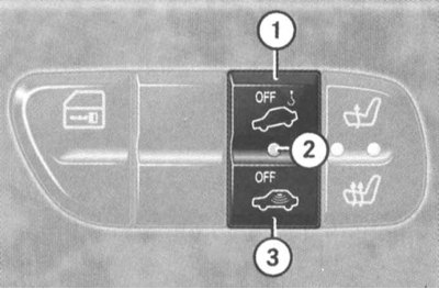
1 — The switch of a mode of protection against towage
2 - Control LED
3 — The switch of ultrasonic control of internal volume
Switches for activating the heating of the right front seat
Note. The principle of controlling the heating of the driver's seat is similar to that described below, the heating element activation buttons are located symmetrically in the upper left group of switches of the console section of the instrument panel (see above).
The buttons for selecting the operating modes of the heating elements of the right front seat are mounted in the right side of the upper right group of switches in the console section of the instrument panel (see illustration The layout of the control components on the console section of the instrument panel).
Make sure the ignition is on.
By means of the top button the mode of normal heating is activated, - one red control light-emitting diode lights up. The lower button is used to activate the accelerated heating of the seat - both red control LEDs are lit.
Seat heating switches
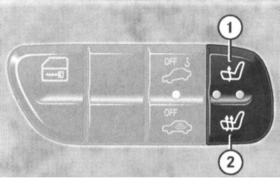
1 - Normal heating
2 - Accelerated heating
To turn off the heating, press the top button until both control LEDs go out.
Note. The seat heating is also switched off when the charging system is overloaded or the battery charge level is insufficient - in this situation, one or both control diodes (depending on the selected heating mode) switch to flash mode. After removing overload (disconnection of excess electricity consumers) the seat heating will be activated automatically.
Air conditioning control panel
See Section Comfort devices.
Control panel for the functioning of the audio system / combined audio-telephone-navigation system COMAND
See vehicle owner's manual.
Switches and controls located on the center console
On the center console of the car there are such controls as the levers of the AT selector and cocking the parking brake, as well as the switches for controlling the functioning of the heating / ventilation system of independent action, additional heater (diesel models) and switching modes of the transfer case (see illustration The layout of the AT control components on the center console).
AT selector lever
See Section Getting Started and Shifting the Automatic Transmission.
The switch of management of functioning of system of heating/ventilation of salon of independent action
see part Comfort devices.
Auxiliary heater operation control switch.
Location of the auxiliary heater rocker switch on the vehicle center console assembly (only diesel models)
1 - Press to deactivate independent heater
2 - Control LED (system activated)
3 - Press to put the heater into standby mode for automatic activation (Stand-by)
Transfer case switch
Attention! When parking, never leave the transfer case in «N», - such a habit is associated with the risk of spontaneous rolling of the car downhill in the event of a failure of the parking brake!
The transfer box is equipped with a two-stage gearbox, providing driving conditions as in normal conditions (mode «H»), as well as in off-road conditions (mode «L»). It is also possible to completely disable the transmission of traction to the wheels of both axles of the vehicle (mode «N»). In both operating modes of the gearbox («H» And «L») the drive is carried out on the wheels of both drive axles. At the same time, in the mode «L» the transfer box gearbox provides increased torque to the driving wheels of the car, almost doubling the gear ratio.
Attention! Do not forget that an increase in tractive effort due to an increase in the gear ratio is always associated with an inversely proportional reduction in the speed of the vehicle!
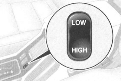
Transfer case switch
The key switch for the transfer case modes is located on the left side of the slanted rear panel of the vehicle's center console. The buck mode must be activated with the engine running and set to «N» selector lever AT and at the speed of movement no more than 40 km/h. Click on the top («LOW») part of the key, - the transfer case gearbox should switch to a lower gear, which is accompanied by the letter flashing «L» in the corresponding field of the base page of the multifunction display of the on-board computer (see Section Instrument cluster, meters, control lamps and indicator lights).
To return to normal driving (overdrive mode) you have to click on the bottom («HIGH») keys (the engine must be running, the AT is in the neutral position, and the speed of the vehicle must be not less than 70 km/h), - in the corresponding field of the base page of the multifunctional display of the on-board computer (see Section Instrument cluster, meters, control lamps and indicator lights) letter should appear «H».
If switching to the on-board computer multifunction display screen fails, one of the following messages is displayed:
- «TC SHIFT CONDITIONS NOT FULFILLED» (Transfer box switching conditions not met), - one or more switching conditions are not fulfilled;
- «TC IN NEUTRAL» (Transfer case moved to neutral position), - the switching process was interrupted, and the transfer case gearbox was switched to the neutral position;
- «TC SHIFT ABORTED» (Gear changeover process interrupted), - Switching failed.
Try again.
To transfer the transfer case gearbox to the neutral position «N» stop the car, turn the ignition key to position 0 and firmly apply the parking brake. Next, depress the foot brake pedal, move the AT selector lever to the position «N», then turn the ignition key to position 1, click on any part («LOW» or «HIGH») mode key switch. If the switch is successful, the corresponding field in the base page of the multifunction display (see Section Instrument cluster, meters, control lamps and indicator lights) the letter will be displayed «N», in addition, a message is displayed on the screen «TC IN NEUTRAL» (Transfer case is in neutral position).
Note. Opening the driver's door of the car with the key left in the ignition and moved to the position «N» transfer case causes the alarm buzzer to sound!
Switches located on the door panels
Switches for adjusting the position of the front seats are placed on the side panels of the front doors, assemblies of switches for controlling the operation of the electric window lifter are mounted in the armrests.
Front door switch assemblies (on the example of a driver's)
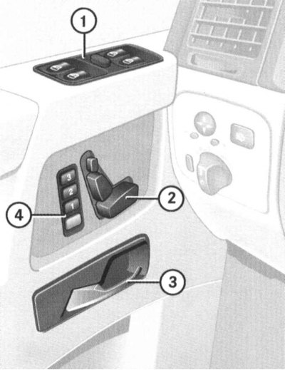
1 - The main panel of switches for controlling the operation of the power window; 2 - Group of switches for adjusting the position of the driver's seat; 4 - Buttons for memorizing and recalling from the memory the parameters for adjusting the driver's seat / steering column / door rear-view mirrors; 3 - Internal door handle
A group of switches for adjusting the seat position/accessing the processor memory
The design of the electric drive allows flexible adjustment of up to five seat parameters - use the appropriate switch section
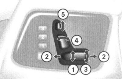
1 - Adjusting the height of the seat; 2 - Adjusting the position of the seat in the longitudinal direction; 3 - Adjusting the inclination of the seat cushion; 4 - Adjusting the angle of the backrest; 5 - Headrest height adjustment
Buttons for storing/recalling seat adjustment parameters
5 - Button for accessing memory for recording
6 - Buttons for recording/calling selected parameters
The switches for adjusting the position of the front seats are located on the side panels of the front doors. The operation of the electric drive is possible only in the positions 1 and 2 ignition switch (on some models also in position 0 with any of the front doors open).
Switches for controlling the functioning of the electric drive of door windows
Note. The power windows operate only when the ignition is on.
Individual switches for controlling the functioning of the power windows are located on each of the side doors of the car.
The main panel for centralized control of the power windows of all doors is mounted in the armrest of the driver's door.
Main switch panel for centralized control of the operation of the door windows
1 - Switch for blocking individual switches for rear window lifters; 2 - Power window of the left front door; 3 - Power window of the right front door; 4 - Power window of the right rear door; 5 - Power window left rear door
Each of the main panel switches allows you to activate the power window regulator drive of the corresponding door. Slide switch placed in the center of the panel by moving it to the right until the symbol appears
To lower/raise the glass, gently press the button of the corresponding switch in the desired direction - releasing the button will stop the glass. Depressing the switch beyond the point of resistance leads to the automatic lowering/raising of the glass of the corresponding door.
Note. If the window encounters resistance when moving to the upper position, the electric drive of the regulator is immediately blocked, while the glass goes down a little, and further holding down the upper part of the key will only lower the window to the lower position.
It is also possible to lower and raise the door windows from the remote control of a single lock.
Switches and controls located on the overhead console and interior rear-view mirror
Layout of switches on the overhead console and interior rear-view mirror assembly
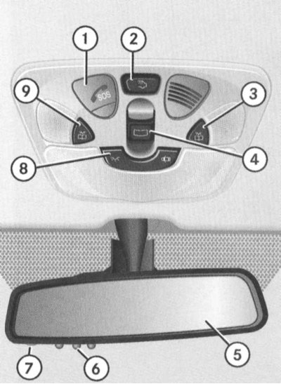
1 - TELE AID system emergency call button; 2 - Button for turning on the luggage compartment lighting; 3 - Button for turning on the right directional individual lamp; 4 - Switch for controlling the functioning of the electric drive of the sliding and lifting sunroof (station wagon models) /drop top (Convertible models); 5 - Cabin rear-view mirror; 6 - Buttons for controlling the functioning of the transmitter of the remote drive of the garage door; 7 - Control LED of the garage door remote drive device; 8 - Switch for selecting the mode of operation of the main salon lighting; 9 - Button for turning on the left directional individual lamp
TELE AID system emergency call button
The button is intended for emergency communication with the dispatcher of the regional rescue service.
Information on activation and deactivation of the service mode of the TELE AID system is given in Part Comfort devices.
Luggage compartment light switch
The luggage compartment is illuminated using a push-button switch mounted in the rear of the overhead console (2). The layout of the rear lights is shown below (see illustration Rear saloon lights are equipped with three-position slide switches). On Wagon models, the luggage compartment lighting is activated automatically when the tailgate is opened, and it is not possible to turn it off from the console switch. In order to avoid recharging the battery when the tailgate is left open for a long time, turn off the lamps: press the button of the lock cylinder of the outer handle of the open rear door, then lower the latch flag down. Removal of blocking is made by repeated pressing the button of the lock cylinder.
Attention! To avoid damage to the lock, do not try to slam the tailgate with the latch flag lowered!
The procedure for turning off the luggage compartment lighting when the tailgate is open on Wagon models
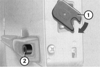
1 - Lock cylinder button
2— Latch flag
Switches for directional individual lamps of the front seats
Two pushbuttons (3 and 9) (see illustration Layout of switches on the overhead console and interior rear-view mirror assembly) are located on the sides of the overhead console and serve to activate side directional lights that provide individual illumination of the driver's and front passenger's seats.
Switch for selecting the operating mode of the main interior lighting
Key switch (8), mounted in the front of the overhead console (see illustration Layout of switches on the overhead console and interior rear-view mirror assembly), has three fixed positions, allowing you to select one of the three modes of operation of the main interior lighting.
Automatic interior lighting activation mode
When the switch is in the middle position, the interior lighting (without luggage compartment) activated automatically at night in the following cases:
- When unlocking door locks;
- When removing the key from the ignition lock;
- When opening the doors, - opening the front doors leads to the activation of only the front salon lamps, the rear ones - only the rear ones, and the door lighting is additionally turned on.
Note. If the doors are left open with the key removed from the ignition, the lights will turn off on a timer signal after approximately 30 minutes.
Closing the doors with the key removed from the ignition lock leads to a slow shutdown of the lamps. To instantly turn off the lights, just insert the key into the ignition.
Note. The function of delayed switching off of interior lighting, at the request of the owner of the car, can be turned off through the menu system of the multifunction display of the on-board computer.
Manual control
If necessary, automatically activated luminaires can be forcibly turned off by pressing the right side of the switch button, marked with the
By pressing the left side of the key, marked with the
Note. Remember that the auto-off function does not apply to directional individual lighting fixtures - do not forget to turn them off manually after use (see above, - front lamps, - and below, - rear).
Sliding/tilting sunroof operation control switch (station wagon models) /drop top (Convertible models)
Note. The electric sunroof / soft top operates only when the ignition is on.
Control slide switch (4) fits in the center of the ceiling console (see illustration Layout of switches on the overhead console and interior rear-view mirror assembly).
Models Station wagon with tilt/slide sunroof
staff management (from console switch)
To move the sunroof cover, push the switch in the direction of the arrows (1 or 2).
Note. Depressing the switch beyond the point of resistance allows the sunroof cover to automatically move to the appropriate end position.
Principle of operation of the slide/tilt sunroof operation control switch on suitably equipped Wagon models
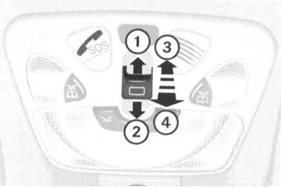
1 - Open
2 - Close
3 - Raise
4 - Lower
Raising and lowering the lid is done by pressing the switch in the direction of the arrows (3 and 4). The principle of operation is the same as for shifting, i.e. when the switch is pressed slightly, the lid will move as long as the key is held down, but to automatically transfer the lid to the extreme positions, press the switch in the appropriate direction overcoming the point of resistance.
In case of failure of the electric drive, the closing of the top hatch cover must be done manually (see below).
Emergency closing of the top hatch cover
The sunroof manual mechanism is located under the left C-pillar trim panel in the vehicle's luggage compartment.
The mechanism for the mechanical emergency closing of the top hatch cover is located under the left rear panel of the luggage compartment upholstery.
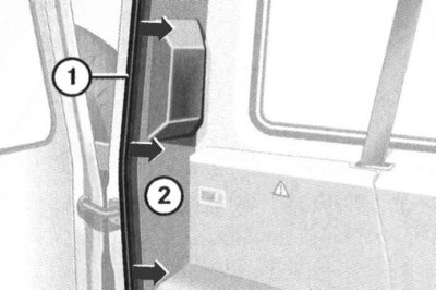
1 - door seal
2 - upholstery panel
Open the tailgate, remove the seal from the corresponding side of the doorway and the left C-pillar trim panel.
Note. On models equipped with additional storage compartments, you must first unscrew the screws securing the rear lining of the additional compartment.
Remove the socket wrench from the on-board tool kit, put it on the drive shaft of the mechanism and start turning it with a screwdriver in the appropriate direction.
Activation of the manual drive mechanism of the upper hatch is carried out using a socket wrench from the on-board kit.
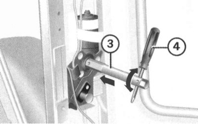
Left Rotation: Open
Right Rotation: Close
Convertible convertible models
Attention! Lowering and raising the convertible top must only be carried out after the vehicle has come to a complete stop! During movement, the convertible top must occupy one of the extreme (lowered or raised) positions - make sure that the convertible top is securely locked while driving!
Attention! In order to avoid recharging the battery, try to avoid repeated activation of the electric convertible top!
Note. A description of the procedures for attaching the protective cover of the convertible top and installing the wind deflector is given in the subsection below «Soft top cover and wind deflector».
When raising/lowering the convertible top, pay attention to the following points:
- In the lowered position, the protective cover must be fully fastened;
- When lowering/raising the convertible top, there must be sufficient free space to move the roof;
- Check that the height of the load placed in the luggage compartment does not exceed the level of the standard position of the protective cover - the luggage should not rest against the cover;
- No objects must be placed on top of the protective cover of the luggage compartment;
- The top rack must not be mounted on the roof of the car;
- Lowering a soiled or wet convertible top is not permitted;
- To avoid damage to the roof material, do not lower the convertible top when the air temperature is below -15°C;
- Before lowering / raising the roof, the car should be parked as close to horizontal as possible.
Staff management (from console switch)
lowering
Make sure the zippers and corner locks of the tailgate are securely fastened.
Move the AT selector lever to position «R».
Engage the parking brake.
Make sure the ignition is on.
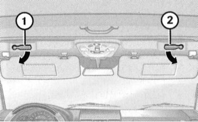
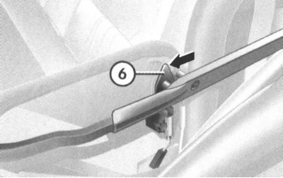
To release the locking of the convertible top, turn down the two locking levers located under the sun visors (1 and 2)
Lower the sun visors and turn the two locking levers located below them in the directions indicated by the arrows - a signal buzzer should sound, confirming that the roof clamps have been released.
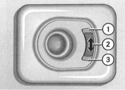
The principle of operation of the power convertible top control switch
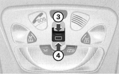
3 - Lower
4 - Raise
Press in the direction of the arrow (3) slide switch on the ceiling panel and hold it in this position until the signal buzzer stops, confirming the end of the roof lowering process.
Return the lock levers located under the sun visors to their original position.
uplift
Move the AT selector lever to position «R».
Engage the parking brake.
Make sure the ignition is on.
Lower the sun visors and deploy the two locking levers below them in the directions indicated by the arrows - a signal buzzer should sound, confirming that the roof locks have been released.
Press in the direction of the arrow (4) slide switch on the roof panel and hold it in this position until the edge of the convertible top stops over the windshield cut.
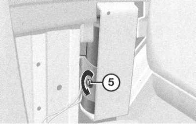
To complete the procedure for lifting the convertible top
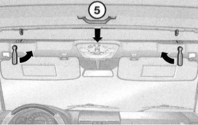
5 - Handle
Pull the roof by the handle (5) so that at least one of the latches snaps into place, then return the appropriate locking lever to its original position. Then turn up the second lever - the alarm buzzer should turn off, thus confirming the successful completion of the roof locking process.
If the electric drive fails, the convertible top can be raised manually (see below).
Emergency closing of the convertible top
Note. An assistant will be required to complete the procedure.
Move the AT selector lever to position «R».
Apply the parking brake and remove the key from the ignition.

Release the convertible top lock. To release the locking of the convertible top, turn down the two locking levers located under the sun visors (1 and 2)
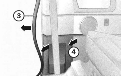
Open the right front door, release the front of the door seal from the pillar «IN» and remove the bottom trim panel «IN».
Use a socket wrench to turn the head of the emergency valve counterclockwise.
Press the locking latches on both sides of the vehicle in the direction indicated by the arrow and simultaneously pull up and open the convertible roof. After the edge of the roof is pulled up to the cut of the windshield, proceed in the same way as with the standard installation of the roof.
Electric Garage Door Remote Control Buttons
The pushbutton switches and the control LED of the electric drive operation control system are built into the interior rear-view mirror assembly (see illustration Layout of switches on the overhead console and interior rear-view mirror assembly).
Switches for rear individual interior lamps
Rear interior lights are equipped with three-position slide switches:
1 - Lamp on
2 - The lamp is off
3 - Automatic control
The slide switches are mounted in the assemblies of the rear individual saloon lamps located on the left and right above the multi-seat rear seat of the car and have three standard positions. The principle of operation of the switches is similar to the principle of operation of the switch for selecting the operating modes of the main salon lighting (see above).
On-board computer (with appropriate equipment)
Detailed information on the rules for using the on-board computer is given in the vehicle operating instructions.