
Instrument cluster
The design of the instrument cluster
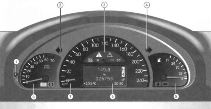
1 - Rotary-push handle for resetting the current mileage meter / adjusting the intensity of instrument illumination; 2 - Control lamp for activating left turn indicators; 3 - Control lamps and light indicators; 4 - Control lamp for activating right turn indicators; 5 - Fuel gauge with built-in SRS warning lamps and «Fasten seat belts»; 6 - Multifunctional display of the on-board computer (base page: odometer/odometer/chronometer/transfer case and AT indicators/outside temperature sensor indicator); 7 - Speedometer; 8 - Tachometer with built-in control lamps for the brake system and ABS
Instrumentation
Instrument cluster activation
The instrument cluster is activated by opening the driver's door, turning the key in the ignition switch to position 1 or 2, pressing the turn-push handle for resetting the current mileage counter (1) and turn on interior lighting (see Section Controls and interior equipment).
Adjusting the intensity of instrument illumination
Adjusting the intensity of instrument lighting (with running lights on - see Section Controls and interior equipment) operated by means of a rotary push-button mounted on the left side of the instrument cluster (1), - using the same handle, the instrument cluster can be activated (see above) and resetting the current mileage counter (see below).
Fuel gauge
Meter (5) located in the right corner of the instrument cluster and serves for visual monitoring of the amount of fuel remaining in the tank.
The error in readings of the fuel gauge is minimal when the car is in a strictly horizontal position. When driving on winding or hilly roads, the error of the instrument increases. The functioning of the meter does not depend on the position of the ignition key. Label 1/1 corresponds to the state of full refueling, R - to an empty tank (with reserve stock). The control lamp built into the dial of the meter with the image of a filling column notifies the driver of the need to refuel the car as soon as possible.
SRS warning lamps are mounted in the lower left corner of the meter dial and «Fasten seat belts» (see below).
Speedometer
The speedometer is placed in the central part of the instrument cluster and shows the vehicle speed in km/h.
Inside the dial of the speedometer there is a panel of control lamps / indicator lights, a multifunctional display of the on-board computer.
Tachometer
The tachometer is located to the left of the speedometer and shows the engine speed in thousands of revolutions per minute (the reading should be multiplied by 100). In order to avoid engine failure, it is forbidden to exceed the maximum permissible speed of the crankshaft (the tachometer needle should never enter the red zone of the scale).
Note. In order to protect the engine, when the crankshaft speed reaches the red marking range, the fuel supply is cut off.
In the lower right corner of the tachometer indicator, there are warning lamps for arming the parking brake / drop in the brake fluid level and ABS (see below).
Display fields of the base page of the multifunction display of the on-board computer
Note. Instructions for using the on-board computer are given in the car's operating manual - ask in automotive literature stores.
Odometer and current mileage counter
The layout of the display fields of the base page of the multifunctional display of the on-board computer
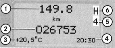
1 - Current mileage counter; 2 - Odometer reading; 3 - Outside air temperature; 4 - Chronometer; 5 - The position of the selector lever / switching range AT; 6 - Indicator of the selected transfer case mode
Odometer display fields (2) and current mileage counter (1) located one above the other in the center of the base page of the multifunction display. The odometer records the total mileage of the vehicle since it was put into service, the resettable current mileage counter allows you to track the mileage of a particular car trip (since the last reset).
To reset the meter readings, activate the instrument cluster, then press the turn-and-push handle mounted in the left corner of the instrument cluster and hold it pressed for about 1 second.
Note. The base page should be cut into the display.
Outside temperature indicator
Display field for outdoor temperature sensor readings (3) located in the lower left corner of the base page of the multifunction display. Temperature is in degrees Celsius (°С).
The change in readings after leaving the garage occurs with a certain delay due to the inertia of the sensor adaptation.
In addition, there is a forced delay in the rise of readings in accordance with an increase in ambient temperature at an engine coolant temperature above 60°C, which helps to prevent interference from a hot engine during stops and when the vehicle is moving at low speeds.
Chronometer
The bottom right corner of the base page of the multifunctional display is reserved for the indication of the onboard chronometer readings. The chronometer setting knob is located on the left under the tachometer dial (see ibid). Turning the regulator pulled out of the panel clockwise leads to an increase in readings, counter-clockwise to a decrease.
Indicator of the position of the selector lever / switching range AT
Field of indication of the current AT range (5) is placed in the upper left corner of the base page of the multifunction display. The symbol corresponding to the selected position of the selector lever AT is displayed in the field («R», «R», «N» or «D»).
Transfer case selected mode indicator
Field of indication of the current mode of the transfer case (6) is placed in the upper left corner of the base page of the multifunction display, directly above the indication field of the current AT range (4). The symbol corresponding to the selected mode of the transfer case is displayed in the field («H», «L» or «N»).
Control lamps and indicator lights
A whole complex of control lamps and indicators is built into the assembly of the car's instrument cluster, with the help of which the driver receives important information about the serviceability / violation of the functioning of the main units and systems of the car. The layout of the control lamps on the instrument panel is shown in the illustration Design of the instrument cluster. Another indicator light (sump filter power system) placed on the center console in front of the AT selector lever.
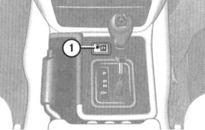
Location of power system filter sump warning light
Below is information on the principle of operation of each of the provided light indicators separately.
List of control lamps and indicator lights included in the instrument cluster
Pilot lamps and light indicators are built into the dials of the instruments in the instrument cluster (The design of the instrument cluster).
Turn Signal/Hazard Indicator Lights
The light indicators designed in the form of arrows have a green glow and serve to monitor the proper functioning of the corresponding direction indicators. The direction of the indicator arrows coincides with the selected direction of change of the vehicle's course. The indicators work in a flashing mode with a frequency corresponding to the frequency of blinking of the direction indicators. Rapid flashing of one of the indicators usually indicates a burnout of the lamp of one of the indicators of the corresponding turn - replace the burned-out lamp as soon as possible so as not to create emergency situations on the roads.
Simultaneous flashing of the indicator lights of both directions is usually accompanied by the activation of the alarm.
Warning lamp of the ABS anti-lock braking system
This warning lamp is used to monitor the correct functioning of the ABS, it works briefly when the ignition is turned on and should go out a few seconds after the engine is started. Failure of the lamp to turn off, as well as its activation while driving, indicates a malfunction of the anti-lock brake system - the car should be immediately driven to a Mercedes-Benz service station for diagnostics and the necessary remedial repairs.
Note. Simultaneously with the ABS, the 4-ETS and ESP systems are also disabled), which must be confirmed by the operation of the corresponding control lamp (see below).
Brake Fluid/Fault Warning/Parking Brake Indicator
The warning lamp illuminates continuously when the parking brake is applied, reminding the driver to release it before driving off. Driving with the parking brake applied leads to rapid overheating and failure of the brake mechanisms of the rear wheels of the car, as well as to premature wear of the rear wheel tire treads, and in addition, it can cause a malfunction of the anti-lock brake system (ABS).
If the warning light stays on after the parking brake is released, or if it comes on while driving, this usually indicates an excessive drop in the brake fluid level - one of the possible reasons for the gradual decrease in the brake fluid level is normal wear of the friction linings of the brake pads.
Note. A short-term operation of the control lamp also occurs when the ignition is switched on (even with the parking brake released).
Anti-slip control warning lamp (4-ETS) /anti-skid (ESP) /anti-lock (ABS) systems
Note. The 4-ETS system is activated at speeds from 40 to 80 km/h when one of the wheels reaches the tire grip limit (for example, with one-sided ice). The corresponding wheel is then braked to ensure reliable traction.
This warning lamp comes on briefly when the ignition is switched on and should go out as soon as the engine is started. The operation of this control lamp is accompanied by the forced shutdown of the anti-skid (ESP) systems (see Sections Anti-slip system (4-ETS), Electronic anti-skid system (ESP)). Failure of the lamp to turn off, as well as its activation while driving, indicates a malfunction of the 4-ETS / ESP / ABS systems, - the car should be immediately driven to a Mercedes-Benz service station for diagnostics and necessary repair repairs. Activating the flashing light while the vehicle is moving alerts the driver that the vehicle's wheels are at the limit of traction and must slow down to a safe level.
Note. In the event of a high brake load, the 4-ETS system is automatically switched off for a short time to prevent overheating of the brakes - this switch-off is accompanied by the activation of the warning lamp.
Attention! When towing a car with the rear wheels off the ground, as well as when checking the proper functioning of the brake mechanisms on the stand, the engine must be turned off, because. Otherwise, the active braking action of the ESP system can lead to failure of the rear wheel brakes!
MIL failure warning lamp («Check engine»)
This warning lamp comes on briefly when the ignition is switched on and should go out a few seconds after the engine is started. Failure of the lamp to turn off, as well as its activation while driving, indicates a malfunction of the engine control systems / reducing the toxicity of exhaust gases - the car should be immediately driven to a Mercedes-Benz service station for diagnostics and necessary remedial repairs.
Note. To turn off the warning lamp activated after refueling a completely empty fuel tank, repeat the procedure for starting the engine three or four times.
Speedtronic activation indicator light
This indicator serves to confirm the activation of the variable speed limiter mode of the tempostat (Speedtronic) (see Section Speed control systems (Tempostat/Speedtronic)).
High Beam Activation Indicator Light
This indicator serves to confirm the activation of the high beam headlights.
Diesel engine preheat warning lamp
The preheating indicator lamp lights up when the ignition is switched on and indicates that the preheating system has been activated. The engine must not be started before the warning lamp turns off.
Indicator light «Fasten your seat belt»
This indicator has an amber glow and briefly (for about 6 seconds) is activated when the ignition is switched on, reminding the driver and passengers to fasten their seat belts.
Additional security warning lamp (SRS)
This warning lamp comes on for approximately 4 seconds when the ignition is switched on and should go out as soon as the engine is started. If the lamp continues to burn while the engine is running (in continuous or flashing mode), this indicates a malfunction of the SRS system components. If equipped, the operation of this warning lamp may indicate a malfunction in the circuits of the side and head airbags, or the devices of the automatic emergency seat belt tensioners.
Control lamp of the moisture separator of the power system
The indicator lamp is placed in front of the upper cover of the center console of the car (see the illustration of the location of the control lamp of the sump filter of the power supply system), to work briefly when the ignition is turned on and serves to warn the driver about the need to perform a procedure to remove moisture from the fuel. If the lamp refuses to turn off after starting the engine or if it turns on while driving, contact a Mercedes-Benz workshop as soon as possible.
Attention! Prolonged use of the vehicle with the water separator warning light on can cause severe internal engine damage, which is not covered by the manufacturer's warranty for refurbishment!